EasyManua.ls Logo

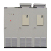
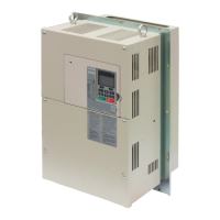
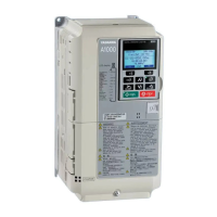
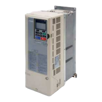
YASKAWA A1000 - User Manual

YASKAWA A1000
52 pages
Print Icon
To Next Page IconTo Next Page
Loading...
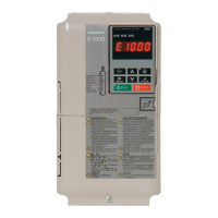
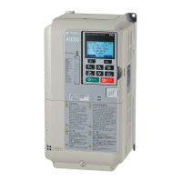
YASKAWA AC Drive A1000
High Performance Vector Control Drive
Quick Start Guide
MANUAL NO. TOEP C710616 27D
Type: CIMR-ACA
Models:
200 V Class: 0.4 to 110 kW
400 V Class: 0.4 to 630 kW
To properly use the product, read this manual thoroughly and retain
for easy reference, inspection, and maintenance. Ensure the end user
receives this manual.

Other manuals for YASKAWA A1000

Questions and Answers

  • L
    Lawrence BeardAug 25, 2025
    Why is my YASKAWA A1000 Controller showing a DC Overvoltage (ov) error?
    • M
      Megan RogersAug 25, 2025
      The most common cause for the YASKAWA Controller DC Overvoltage (ov) error is when the DC bus voltage rises too high. This can occur if the deceleration time is too short, stall prevention is disabled, the braking chopper/resistor is broken, there's unstable motor control in OLV, or the input voltage is too high. To resolve this, try increasing the deceleration time, enabling stall prevention via parameter L3-04, ensuring the braking resistor and chopper are functioning correctly, checking and adjusting motor parameter settings, and verifying the power supply voltage meets the drive's specifications.
  • J
    jamescervantesSep 4, 2025
    What does Option External Fault EF0 mean on YASKAWA A1000 Controller?
    • D
      David WilsonSep 4, 2025
      If the YASKAWA Controller displays an Option External Fault (EF0) error, it indicates that an external fault was tripped by the upper controller via an option card. To resolve this, remove the fault cause, reset the fault, restart the drive, and check the upper controller program.
  • J
    Jennifer JonesSep 3, 2025
    How to fix Controller Undervoltage Uv2 on YASKAWA A1000?
    • S
      Sheila SalazarSep 4, 2025
      If the YASKAWA Controller displays a Controller Undervoltage (Uv2) error, it means the drive's controller power supply voltage is too low. To resolve this, cycle power to the drive and check if the fault reoccurs. If the fault continues, replace the drive.
  • M
    Michael DavidsonSep 3, 2025
    What causes Input Phase Loss LF on YASKAWA Controller?
    • J
      Jerome JohnsonSep 3, 2025
      If the YASKAWA Controller displays an Input Phase Loss (LF) error, it means there is an input voltage drop or phase imbalance, one of the input phases is lost, or there are loose wires at the drive input. To resolve this, check the power supply and ensure that all cables are properly fixed to the correct terminals.
  • K
    Krystal LittleSep 3, 2025
    Why am I getting DC Undervoltage Uv1 on my YASKAWA A1000?
    • B
      brian31Sep 3, 2025
      If the YASKAWA Controller displays a DC Undervoltage (Uv1) error, it means the voltage in the DC bus fell below the undervoltage detection level. This can occur due to a power supply failure, loss of an input phase, or an insufficient power supply. To resolve this, check the power supply and ensure it is strong enough.
  • S
    Susan JordanSep 2, 2025
    What does Output Phase Loss PF mean on YASKAWA A1000?
    • D
      Donald BaileySep 3, 2025
      If the YASKAWA Controller displays an Output Phase Loss (PF) error, it indicates that the output cable is disconnected, the motor winding is damaged, there are loose wires at the drive output, or the motor is too small. To resolve this, check the motor wiring, ensure all terminal screws in the drive and motor are properly tightened, and verify the motor and drive capacity.
  • K
    Katherine EsparzaSep 2, 2025
    What does External Fault EF on YASKAWA Controller indicate?
    • J
      Justin DuncanSep 2, 2025
      If the YASKAWA Controller displays an External Fault (EF) error, it means that forward and reverse commands were input simultaneously for longer than 500 ms, stopping a running motor. To fix this, check the sequence to ensure that forward and reverse inputs are not set at the same time.
  • H
    Hannah LongSep 2, 2025
    What to do for Drive Overload oL2 on YASKAWA A1000 Controller?
    • A
      Amanda Gates DDSSep 2, 2025
      If the YASKAWA Controller displays a Drive Overload (oL2) error, it means the load is too heavy, the drive capacity is too small, or there's too much torque at low speed. To resolve this, check the load, ensure the drive is adequately sized for the load, and reduce the load or increase the drive size, as the overload capability is reduced at low speeds.
  • E
    Erik CarpenterSep 1, 2025
    What does Control Fault CF mean on YASKAWA A1000 Controller?
    • L
      Lauren GriffinSep 1, 2025
      If the YASKAWA Controller is showing a Control Fault (CF) error, it means the torque limit was reached during deceleration for longer than 3 seconds in Open Loop Vector control. This can happen if the load inertia is too big, the torque limit is too low, or the motor parameters are wrong. You should check the load, set the torque limit to the most appropriate setting (L7-01 through L7-04), and check the motor parameters.
  • E
    Elizabeth FernandezSep 1, 2025
    What causes Ground Fault GF on YASKAWA A1000?
    • C
      Carol RuizSep 1, 2025
      If the YASKAWA Controller displays a Ground Fault (GF) error, it indicates that ground leakage current has exceeded 50% of the drive's rated output current, cable or motor insulation is broken, or there's excessive stray capacitance at the drive output. To fix it, check the output wiring and motor for short circuits or broken insulation, replace any damaged parts, and reduce the carrier frequency.

Summary

YASKAWA AC Drive A1000 Quick Start Guide

Safety Instructions and General Warnings

Essential safety information, warnings, and precautions for operating the drive.

Applicable Documentation

List of other manuals and documents relevant to the A1000 series drives.

General Warnings

Critical safety warnings for drive installation, operation, and servicing.

Electrical Shock Hazard

Warnings and precautions related to the risk of electrocution.

Sudden Movement Hazard

Warnings about unexpected motor movement during operation or tuning.

Fire Hazard

Warnings and precautions related to fire risks during installation and operation.

Crush Hazard

Warnings about potential crushing injuries during handling or installation.

Burn Hazard

Warnings about potential burns from hot components after operation.

Equipment Hazard

Warnings regarding potential damage to the drive or connected equipment.

Precautions for CE Low Voltage Directive Compliance

Conditions to maintain CE compliance when using the drive with other devices.

Mechanical Installation

Upon Receipt

Initial inspection and verification steps after receiving the drive.

Installation Environment

Recommended environmental conditions for optimal drive performance.

Installation Orientation and Spacing

Guidelines for mounting the drive and required ventilation clearances.

Installation Procedures for Large Models

Specific instructions for installing high-capacity drive models.

Dimensions

Physical dimensions and specifications for different drive enclosure types.

IP20;NEMA Type 1 Enclosure Drives

Dimensional data for drives with IP20/NEMA Type 1 enclosures.

IP00 Enclosure Drives

Dimensional data for drives with IP00 enclosures.

Electrical Installation

Main Circuit Wiring

Instructions and precautions for wiring the main power circuit.

Wiring Specification

Table detailing recommended wiring specifications for the main circuit.

Main Circuit

Guidelines for wiring the main circuit using specified fuses and filters.

Wiring the Main Circuit Input

Precautions for connecting the main circuit power input.

Wiring the Main Circuit Output

Precautions for connecting the main circuit output to the motor.

Ground Connection

Precautions and best practices for grounding the drive unit.

Main Circuit Terminals

Description of main circuit terminal functions and types.

Input Fuse Installation

Recommended fuses for branch circuit protection according to UL standards.

Control Circuit Wiring

Instructions and precautions for wiring the control circuit.

Tightening Torque Values

Recommended torque values for tightening main circuit terminals.

EMC Filter Installation

Guidelines for installing EMC filters to comply with EMC standards.

Control Circuit Wiring Precautions

Important considerations and precautions for control circuit wiring.

Control Circuit Terminals

Overview of the control circuit terminal layout and DIP switches.

Control Circuit Terminal Functions

Detailed description of the functions of each control circuit terminal.

Low Voltage Wiring for Control Circuit Terminals

Wiring practices for low voltage control circuits per NEC standards.

Drive Short-Circuit Rating

Information on the drive's suitability for circuits with specific RMS amperes.

Keypad Operation

Digital Operator and Keys

Overview of the digital operator used for programming and control.

Keys and Functions

Detailed description of each key on the digital operator and its functions.

Menu Structure and Modes

Visual guide to the operator's menu structure and navigation.

Start Up

Drive Setup Procedure

Step-by-step guide for the initial setup and configuration of the drive.

Power On

Precautions to take before and after turning on the drive's power supply.

Control Mode Selection (A1-02)

Guidance on selecting the appropriate control mode for the application.

Normal; Heavy Duty Selection (C6-01)

How to set the drive's duty rating based on application load requirements.

Auto-Tuning (T1-00)

Procedures for automatically setting motor parameters for optimal performance.

Rotational Auto-Tuning for V;f Control

Specific auto-tuning method for V/f control applications.

External Reference Selection and Acceleration; Deceleration Times

Configuring external references and setting acceleration/deceleration times.

Run Command Selection (b1-02)

Parameter setting for determining the source of the run command.

Acceleration; Deceleration Times and S-Curves

Adjusting acceleration, deceleration times, and S-curve profiles.

Reference and Run Source

Defining LOCAL and REMOTE modes for frequency reference and run commands.

I;O Setup

Configuration of digital and analog input/output signals.

Multi-Function Digital Inputs (H1-□□)

Assigning functions to multi-function digital input terminals.

Multi-Function Digital Outputs (H2-□□)

Assigning functions to multi-function digital output terminals.

Multi-Function Analog Inputs (H3-□□)

Configuring the functions and signal levels of analog inputs.

Multi-Function Analog Outputs (H4-□□)

Configuring the functions and signal levels of analog outputs.

Test Run

Steps for performing a test run after initial drive setup.

Parameter Table

Initialization Parameters

Parameters for drive initialization and access level selection.

Control Method Selection (A1-02)

Parameter to select the drive's control mode (V/f, OLV, CLV).

Initialize Parameters (A1-03)

Parameters for initializing drive settings and error resets.

Operation Mode Selection

Parameter for selecting drive operation modes.

Frequency Reference Selection 1 (b1-01)

Parameter to set the source for the frequency reference signal.

Run Command Selection 1 (b1-02)

Parameter to set the source for the run command signal.

Stopping Method Selection (b1-03)

Parameter to define the drive's stopping method.

Phase Order Selection (b1-14)

Parameter to reverse motor direction by changing phase order.

DC Injection Braking

Parameters related to the DC injection braking function.

Carrier Frequency Selection

Parameter to select the carrier frequency and PWM mode.

Frequency Reference

Parameters for setting and adjusting frequency references.

Motor Rated Current

Parameter for inputting the motor's rated current.

Motor Rated Slip

Parameter for inputting the motor's rated slip.

Multi-Function Digital Inputs

Parameters for configuring the functions of digital input terminals.

Multi-Function Analog Inputs

Parameters for configuring the functions and signal levels of analog inputs.

Multi-Function Analog Outputs

Parameters for configuring the functions and signal levels of analog outputs.

Motor Protection

Parameters for the drive's electronic motor overload protection.

Stall Prevention

Parameters to prevent motor stall during operation and deceleration.

Induction Motor Auto-Tuning

Parameters related to the auto-tuning process for induction motors.

Fault Trace

Parameters for tracing and displaying information about previous faults.

Monitor

Parameters for monitoring various drive operating statuses.

Fault History

Parameters for viewing the history of past faults.

DI;DO Sel.

Parameter for selecting digital input and output functions.

Troubleshooting

General Fault and Alarms

Common faults, alarms, causes, and corrective actions for drive operation.

Base Block (bb)

Troubleshooting steps for base block faults related to input status.

Control Fault (CF)

Troubleshooting control circuit faults caused by torque limits or motor parameters.

Control Circuit Fault (CPF02 to CPF24)

Troubleshooting control circuit faults related to drive connectivity.

Control Circuit Fault (CPF25)

Troubleshooting control circuit faults when the terminal board is disconnected.

Cannot Reset (CrST)

Troubleshooting issues where faults cannot be reset.

Option External Fault (EFO)

Troubleshooting external faults triggered by an option card.

External Fault (EF)

Troubleshooting external faults triggered by input signals.

External Faults (EF1 to EF8)

Troubleshooting specific external fault inputs.

Ground Fault (GF)

Troubleshooting ground leakage faults and insulation issues.

Safe Disable (Hbb)

Troubleshooting issues with the Safe Disable input function.

Safe Disable Fault (HbbF)

Troubleshooting faults related to the Safe Disable function.

Output Phase Loss (PF)

Troubleshooting faults related to output phase loss or motor damage.

Overcurrent (OC)

Troubleshooting overcurrent faults.

Heatsink Overheat (oH or oH1)

Troubleshooting issues with heatsink overheating.

Motor Overload (oL1)

Troubleshooting motor overload conditions.

Drive Overload (OL2)

Troubleshooting drive overload conditions.

DC Overvoltage (OV)

Troubleshooting faults related to excessive DC bus voltage.

Input Phase Loss (LF)

Troubleshooting faults related to input phase loss or imbalance.

Braking Transistor Fault (rr)

Troubleshooting faults related to the internal braking transistor.

Thermistor Disconnect (THo)

Troubleshooting faults related to the motor thermistor connection.

DC Undervoltage (Uv1)

Troubleshooting faults related to low DC bus voltage.

Controller Undervoltage (Uv2)

Troubleshooting faults related to low controller power supply voltage.

DC Charge Circuit Fault (Uv3)

Troubleshooting faults related to the DC bus charge circuit.

Operator Programing Errors

Errors arising from incorrect parameter settings via the operator.

Auto-Tuning Errors

Errors encountered during the auto-tuning process for motor parameters.

Acceleration error

Troubleshooting faults where the motor fails to accelerate as specified.

Motor speed fault

Troubleshooting faults related to motor speed.

Current detection error

Troubleshooting faults related to current detection.

Leakage Inductance Error

Troubleshooting errors related to drive's leakage inductance tuning.

Excessive V;f Setting

Troubleshooting faults caused by excessive V/f settings during auto-tuning.

Motor iron-core saturation alarm

Troubleshooting alarms related to motor iron-core saturation.

Rated current alarm

Troubleshooting alarms related to the motor's rated current.

Adjusted Slip Calculation Error

Troubleshooting errors in the calculation of adjusted slip.

Resistance Tuning Error

Troubleshooting errors in resistance tuning calculations.

Leakage Inductance Alarm

Troubleshooting alarms related to leakage inductance calculations.

No-Load Current Alarm

Troubleshooting alarms related to the no-load current.

Safe Disable Input Function

Specifications

Technical specifications for the Safe Disable input function.

Precautions

Critical safety warnings and precautions for using the Safe Disable function.

Using the Safe Disable Function

Information on implementing and utilizing the Safe Disable feature.

Safe Disable Circuit

Description of the Safe Disable circuit components and operation.

Disabling and Enabling the Drive Output (Safe Torque Off)

Explanation of how the Safe Disable function disables drive output (Safe Torque Off).

Returning to Normal Operation after Safe Disable

Procedure to resume normal operation after Safe Disable is activated.

Safe Disable Monitor Output Function and Digital Operator Display

Monitor functions and digital operator display indicators for Safe Disable.

Safe Disable Status Monitor

Monitoring the status feedback signal of the Safe Disable circuit.

UL Standards

UL Standards Compliance

Information on UL and cUL marks and product safety certifications.

Installation Area

Requirements for installation environment to comply with UL standards.

Main Circuit Terminal Wiring

UL-compliant wiring practices and recommendations for main circuit terminals.

Closed-Loop Crimp Terminal Recommendations

Recommended crimp terminals and tools for UL/cUL compliance.

Input Fuse Installation

Recommended fuses for UL compliant branch circuit protection.

Drive Motor Overload Protection

UL recognized electronic motor overload protection features.

E2-01 Motor Rated Current

Parameter for setting the motor's rated current for overload protection.

L1-01 Motor Overload Protection Selection

Parameter to select the type of motor overload protection curve.

L1-02 Motor Overload Protection Time

Parameter to set the time duration for motor overload protection.

Precautionary Notes on External Heatsink (IP00 Enclosure)

Safety notes for IP00 enclosures concerning external heatsinks and capacitors.

Revision History

YASKAWA A1000 Specifications

General IconGeneral
TypeAC Drive
SeriesA1000
Input Voltage200-240V, 380-480V
Frequency Range0-400 Hz
Horsepower Range0.5 to 1000 HP
Power Range0.4 to 630 kW
Control MethodV/f Control
Overload Capacity150% for 60 seconds
BrakingDynamic Braking
CommunicationModbus
SafetySafe Torque Off (STO)
Protection FeaturesOvercurrent, Overvoltage, Undervoltage, Overheat
Operating Temperature-10 to +50°C
Storage Temperature-20 to 60°C
Humidity5 to 95% RH (non-condensing)
EnclosureIP20

Related product manuals