Parameter Details
2
2.4 C: Tuning
YASKAWA TOEPYAIGA5002A GA500 DRIVE PROGRAMMING 217
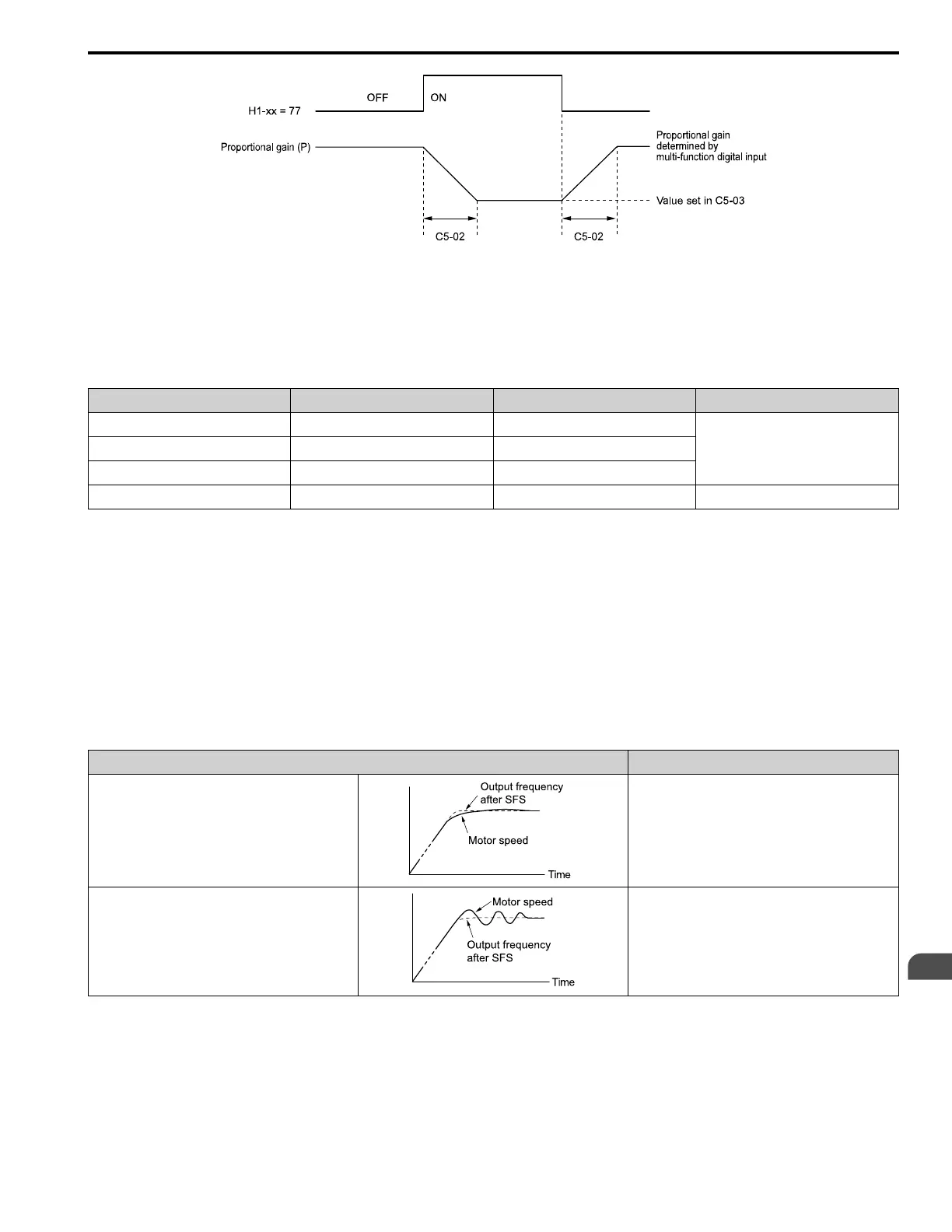
Figure 2.39 Proportional Gain through Multi-function Digital Input Switch
■ Speed Waveform Monitoring Method
To make small adjustments of ASR parameters, monitor the speed waveforms when you make the adjustments. Table
2.30 shows example settings of parameters to monitor speed waveforms.
Table 2.30 Example Settings of MFAO Terminals to Monitor Speed Waveforms
No. Name Setting Value Description
H4-01 Terminal AM Analog Output Select 116 Lets you use terminal AM to monitor U1-16
[SFS Output Frequency].
H4-02 Terminal AM Analog Output Gain 100.0%
H4-03 Terminal AM Analog Output Bias 0.0%
H4-07 Terminal AM Signal Level Select 0 Lets you monitor in a 0 V to 10 V range.
Based on this setting, MFAO terminal AM outputs the output frequency after SFS in a 0 V to 10 V (0% to 100%)
range. The MFAO common is terminal AC:
Yaskawa recommends that you monitor the output frequency after SFS and the motor speed for delays in response
and differences in reference values.
■ Adjust ASR Parameters
Use Table 2.31 to adjust ASR. The table lists parameters for motor 1. You can make the same changes to motor 2
parameters when you run a second motor.
Note:
When adjusting the proportional gain and integral time, adjust the proportional gain first.
Table 2.31 ASR Response and Possible Solutions
Problem Possible Solutions
Speed response is slow.
• Increase C5-01/C5-03 [ASR Proportional Gain].
• Decrease C5-02/C5-04 [ASR Integral Time].
Overshoot or undershoot occurs at the end of acceleration
or deceleration.
• Decrease C5-01/C5-03.
• Increase C5-02/C5-04.

 Loading...


