2.9 L: Protection Functions
378 YASKAWA TOEPYAIGA5002A GA500 DRIVE PROGRAMMING
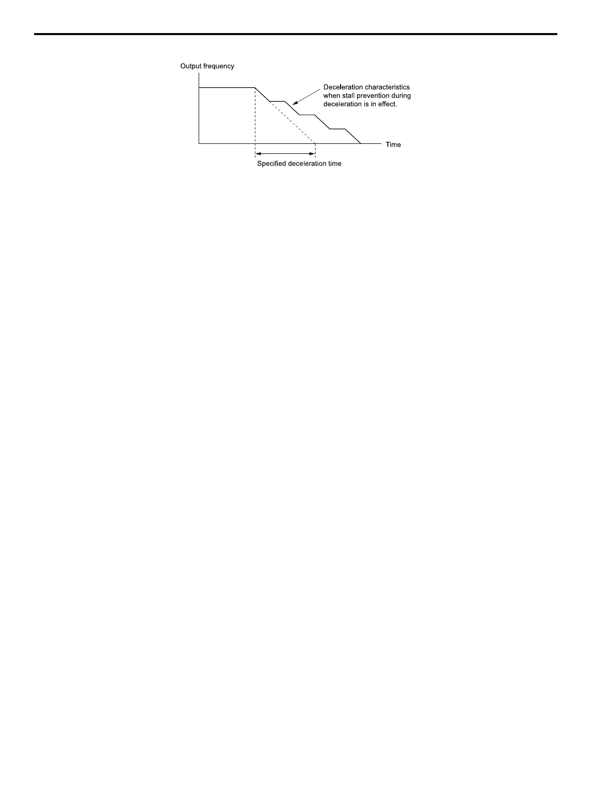
Figure 2.114 shows the Stall Prevention during deceleration function.
Figure 2.114 Stall Prevention Operation during Deceleration
2 : Intelligent (Ignore Decel Ramp)
The drive adjusts the deceleration rate to keep the DC bus voltage at the L3-17 [DC Bus Regulation Level] level. This
makes the shortest possible deceleration time and will not let the motor stall. The drive ignores the selected
deceleration time and the possible deceleration time cannot be less than 1/10 of the set deceleration time.
This function uses these parameters to adjust the deceleration rate:
• L3-20 [DC Bus Voltage Adjustment Gain]
• L3-21 [OVSuppression Accel/Decel P Gain]
• L3-24 [Motor Accel Time @ Rated Torque]
• L3-25 [Load Inertia Ratio]
Note:
The deceleration time is not constant. For applications where the precision of the stop position is very important, use a dynamic braking
option and set L3-04 = 0. If an ov occurs, set L3-04 = 3.
3 : General Purpose w/ DB resistor
A braking resistor is necessary for this setting. The braking resistor and the drive work together for the Stall
Prevention during deceleration function.
4 : Overexcitation/High Flux 1
Enables Overexcitation/High Flux and enables a shorter deceleration time than when L3-04 = 0.
Note:
• If the overexcitation time is long and you decelerate frequently, the drive can detect oL1 [Motor Overload] faults. If the drive detects oL1,
decrease the deceleration time or install a braking resistor to the drive.
• The deceleration time during Overexcitation Deceleration changes when the motor characteristics and machine inertia change. Adjust the
n3-13 [OverexcitationBraking (OEB) Gain] and n3-23 [Overexcitation Braking Operation] levels. Refer to Overexcitation Deceleration on
page 408 for more information.
5 : Overexcitation/High Flux 2
Enables Overexcitation/High Flux 2. This function decreases the possible deceleration time more than Overexcitation/
High Flux.
The drive decreases motor speed and tries to keep the DC bus voltage at the L3-17 level.
If the drive detects oL1, decrease the values set in n3-13 and n3-21. If the drive detects ov, increase the values set in
C1-02, C1-04, C1-06, and C1-08 [Deceleration Times].
Note:
• During Overexcitation/High Flux 2, the drive disables Hunting Prevention in V/f Control and also disables Speed Control that uses torque
limit in OLV Control.
• Refer to Overexcitation Deceleration on page 408 for more information.
7 : Overexcitation/High Flux 3
If you set L3-04 = 7 [Overexcitation Braking 3], the overexcitation increases compared with 4 [Overexcitation/High
Flux]. This can decrease the deceleration time.
Note:
When L3-04 = 7, the overexcitation current increases as compared with 4. Motor load becomes larger, and it can cause oL1 [Motor
Overload]. When you can use L3-04 = 4 to operate the drive, set L3-04 = 4.

 Loading...


