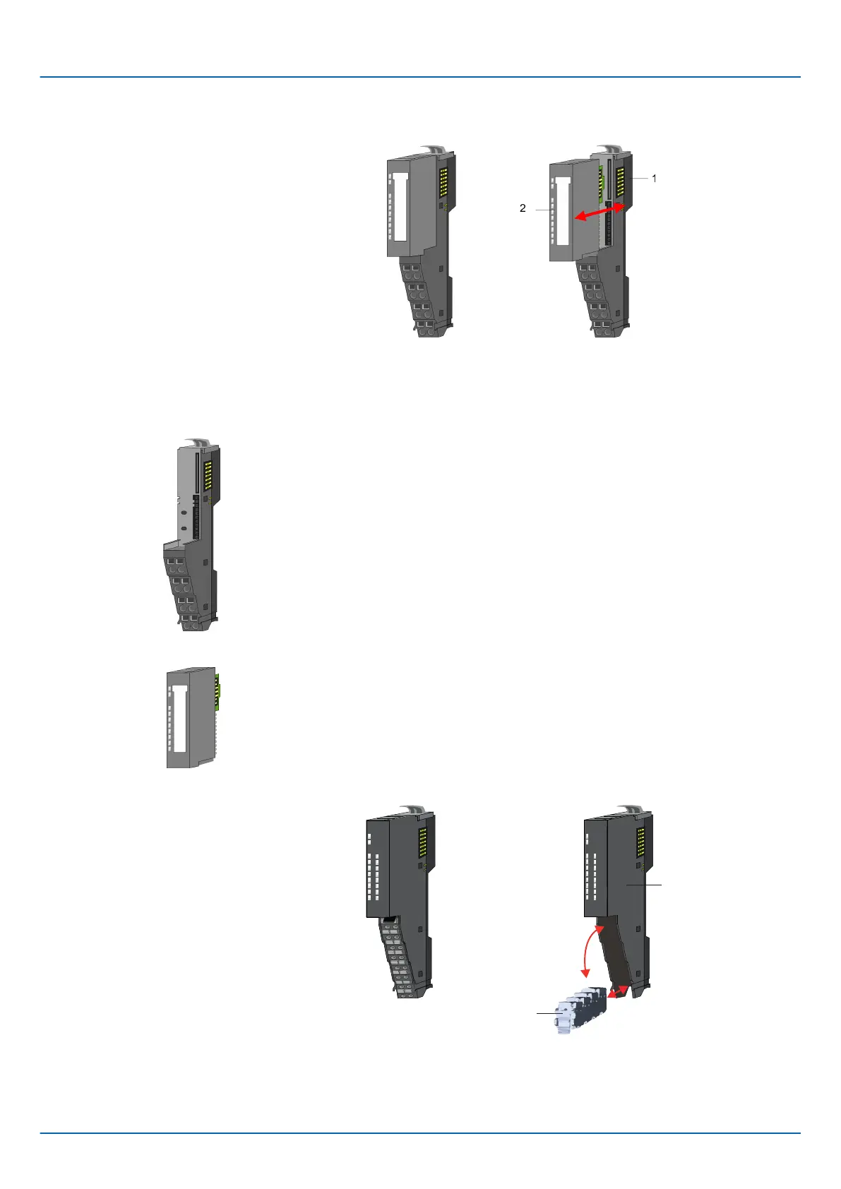
Each 8x periphery module consists of a terminal and an electronic module.
1 Terminal module
2 Electronic module
The terminal module serves to carry the electronic module, contains the backplane bus
with power supply for the electronic, the DC 24V power section supply and the staircase-
shaped terminal for wiring. Additionally the terminal module has a locking system for
fixing it at a mounting rail. By means of this locking system your system may be assem-
bled outside of your switchgear cabinet to be later mounted there as whole system.
The functionality of a periphery module is defined by the electronic module, which is
mounted to the terminal module by a sliding mechanism. With an error the defective elec-
tronic module may be exchanged for a functional module. Here the wiring persists. At the
front side there are LEDs for status indication. For easy wiring, you will find the corre-
sponding connection information for each electronic module on the front and on the side.
Each 16x periphery module consists of an electronic unit and a terminal block.
1 Electronic unit
2 Terminal block
8x periphery modules
Terminal module
Electronic module
16x periphery modules
iC9200 Series
Basics and mounting
System conception > Components
HB700 | CPU | PMC921xEx | en | 23-06 12

 Loading...


