4.2 CPU Module Specifications
4.2.7 System Register Specifications
4-25
Interrupt Status
The data in these registers give the status of information provided by interrupts from each I/O
Module.
Register Configuration
Details
The following table gives details on the Interrupt Module.
Name Register Address Remarks
Interrupt Detection Count SW00698 −
Module Where an Interrupt
Occurred
SW00699 Number of Modules with a single interrupt
Interrupt Modules
SW00700 to
SW00702
Interrupt Module 1
Refer to the following
section for details.
Details on page 4-
25
SW00703 to
SW00705
Interrupt Module 2
SW00787 to
SW00789
Interrupt Module 30
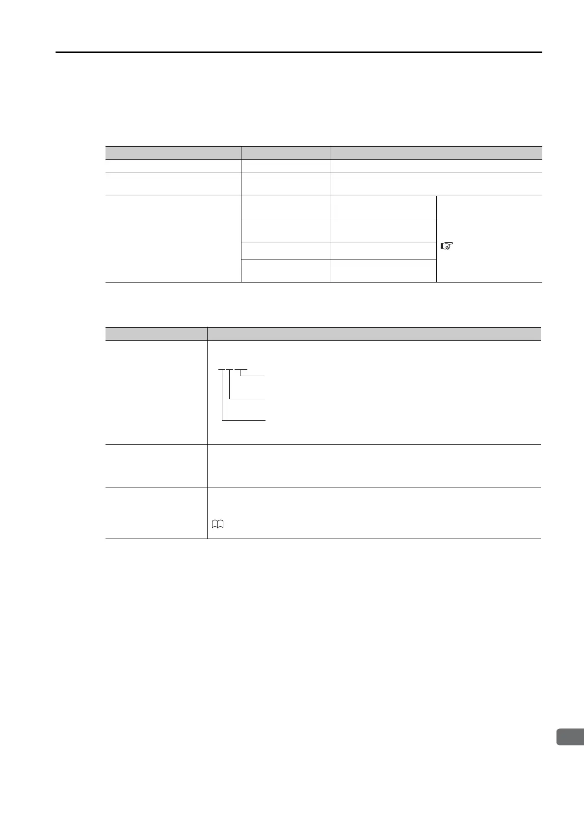
Register Address Remarks
SW007 + 0
Rack No., Unit No., Slot No.
SW007 + 1
Interrupt Type
1: Reserved for system.
2: DI interrupt for LIO-01, LIO-02, LIO-04, or LIO-05
3: Counter interrupt for LIO-01, LIO-02, LIO-06, or CNTR-01
SW007 + 2
Register value for hardware interrupt cause
The contents depends on the hardware that is being used. Refer to the following
manual for details.
MP3000 Series MP3200/MP3300 Troubleshooting Manual
(Manual No.: SIEP C880725 01)
01 to 09: Gives the slot number where the Module in which the
interrupt occurred is mounted.
1 to 4: Gives the unit number of the Module in which the interrupt
occurred is mounted.
1 to 7: Gives the Rack number where the Module in which the
interrupt occurred is mounted.

 Loading...


