Sigma II User’s Manual Chapter 5: Parameter Settings and Functions
5-56
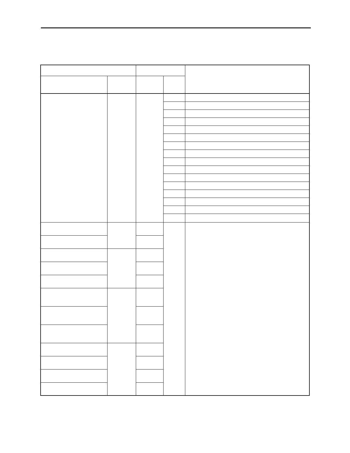
Allocating Other Input Signals
Input signal allocation can be changed as shown below.
Note: "Same as above” means that input signals and terminals SI0 to SI6 are enabled or disabled
through parameter settings 0 to 8.
Input Signal Parameter
Description
Name
Applicable
Logic
Number Setting
Proportional Control Reference
(/P-CON)
ON
(low level)
Pn50A.2
0 Inputs the specified signal from SI0 (CN1-40).
1 Inputs the specified signal from SI1 (CN1-41).
2 Inputs the specified signal from SI2 (CN1-42).
3 Inputs the specified signal from SI3 (CN1-43).
4 Inputs the specified signal from SI4 (CN1-44).
5 Inputs the specified signal from SI5 (CN1-45).
6 Inputs the specified signal from SI6 (CN1-46).
7 Sets the specified signal to always enabled.
8 Sets the specified signal to always disabled.
9 Inputs the specified inverse signal from SI0 (CN1-40).
A Inputs the specified inverse signal from SI1 (CN1-41).
B Inputs the specified inverse signal from SI2 (CN1-42).
C Inputs the specified inverse signal from SI3 (CN1-43).
D Inputs the specified inverse signal from SI4 (CN1-44).
E Inputs the specified inverse signal from SI5 (CN1-45).
F
Inputs the specified inverse signal from SI6 (CN1-46).
Forward Run Prohibit
(P-OT)
OFF
(high level)
Pn50A.3
0 to F Same as above.*
Reverse Run Prohibit
(N-OT)
Pn50B.0
Alarm Reset
(/ARM-RST)
ON
(low level)
Pn50B.1
Forward Current Limit
(/P-CL)
Pn50B.2
Reverse Current Limit
(/N-CL)
Pn50B.3
Contact Input Speed Control
Selection
(/SPD-D)
—
Pn50C.0
Contact Input Speed Control
Selection
(/SPD-A)
Pn50C.1
Contact Input Speed Control
Selection
(/SPD-B)
Pn50C.2
Control Mode Selection
(/C-SEL)
ON
(low level)
Pn50C.3
Zero Clamp
(/ZCLAMP)
Pn50D.0
Reference Pulse Inhibit
(/INHIBIT)
Pn50D.1
Gain Switching
(/G-SEL)
Pn50D.2

 Loading...


