Sigma II User’s Manual Chapter 6: Servo Adjustment
6 - 15
6.2.5 Using Mode Switch
Use the mode switch function for the following purposes.
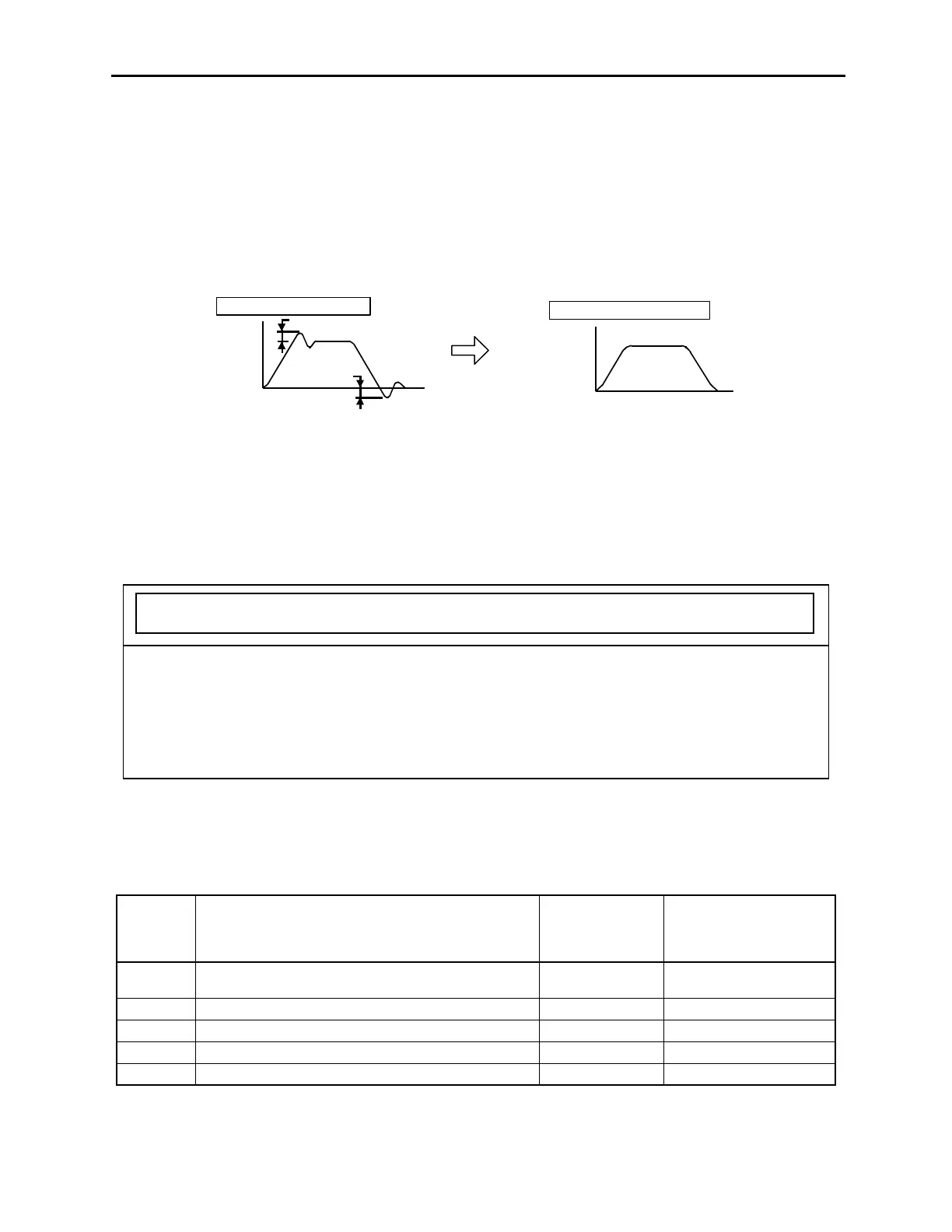
• To suppress overshoot during acceleration or deceleration (for speed control).
• To suppress undershoot during positioning and to shorten the setting time (for
position control).
The mode switch function makes it possible to automatically switch the servo
amplifier’s internal speed control mode from PI to P control mode and vice versa
when specified conditions are satisfied.
Definition:PI control means proportional/integral control, and P control means proportional control. In
effect, switching “from PI control to P control” reduces effective servo gain, thereby making the
servo system more stable.
Selecting Mode Switch Setting
The servo amplifier incorporates four mode switch settings (0 to 3). Select a mode
switch with the following parameter (Pn10B.0).
1. The mode switch is used to fully utilize performance of a servodrive to achieve very high-speed position-
ing. The speed response waveform must be observed to adjust the mode switch.
2. For normal use, the speed loop gain and position loop gain set by auto-tuning provide sufficient speed/posi-
tion control. Even if overshoot or undershoot occurs, it can be suppressed by setting either:
• The acceleration/deceleration time constant for the host device.
• The soft start time constants (Pn305, Pn306)
• The position reference acceleration/deceleration constant (Pn204) for the servo amplifier.
Pn10B.0
Setting
Description
Parameter
Used to Set
Detection Point
Setting Unit
0
Uses torque reference as the detection point.
(Standard setting).
Pn10C
Percentage of rated
torque (%)
1 Uses speed reference input as the detection point. Pn10D Motor Speed (rpm)
2 Uses acceleration as the detection point. Pn10E
× 10rpm/s
3 Uses error pulse input as the detection point. Pn10F Reference unit
4 Mode Switch function is not used. — —
Overshoot
Undershoot
Motor
speed
Time
No mode switch function
With mode switch function
Motor
speed
Time

 Loading...


