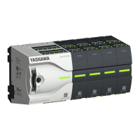
If more modules are connected to the CPU
Ä
‘Option: CPU replacement in a system’
on page 24. If no other modules are connected to the CPU, the CPU is replaces
according to the following proceeding:
1. Pull the locking levers of the CPU outwards until these engage audible.
2. Remove the CPU with a rotation upwards from the mounting rail.
3. Pull the locking levers of the CPU outwards until these engage audible.
CAUTION!
It is not allowed to mount the module sideways on the mounting rail,
as otherwise the module may be damaged!
4. Plug the CPU from the top onto the mounting rail and turn the periphery module
downward until it rests on the mounting rail.
CPU replacement (stand-
alone)
VIPA System MICRO
Basics and mounting
Demounting > Demounting CPU
HB400 | CPU | M13-CCF0000 | en | 16-47 23

 Loading...