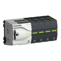
Order no. M13-CCF0000
Current consumption from load voltage L+ (without load) 25 mA
Rated value DC 24 V
Input voltage for signal "0" DC 0...5 V
Input voltage for signal "1" DC 15...28.8 V
Input voltage hysteresis -
Frequency range -
Input resistance -
Input current for signal "1" 3 mA
Connection of Two-Wire-BEROs possible
ü
Max. permissible BERO quiescent current 0.5 mA
Input delay of "0" to "1" 3 µs – 15 ms / 0.5 ms – 15 ms
Input delay of "1" to "0" 3 µs – 15 ms / 0.5 ms – 15 ms
Number of simultaneously utilizable inputs horizontal con-
figuration
16
Number of simultaneously utilizable inputs vertical configu-
ration
16
Input characteristic curve IEC 61131-2, type 1
Initial data size 16 Bit
Technical data digital outputs
Number of outputs 12
Cable length, shielded 1000 m
Cable length, unshielded 600 m
Rated load voltage DC 24 V
Reverse polarity protection of rated load voltage
ü
Current consumption from load voltage L+ (without load) 20 mA
Total current per group, horizontal configuration, 40°C 6 A
Total current per group, horizontal configuration, 60°C 6 A
Total current per group, vertical configuration 6 A
Output voltage signal "1" at min. current L+ (-0.8 V)
Output voltage signal "1" at max. current L+ (-0.8 V)
Output current at signal "1", rated value 0.5 A
Output current, permitted range to 40°C 5 mA to 0.6 A
Output current, permitted range to 60°C 5 mA to 0.6 A
Output current at signal "0" max. (residual current) 0.5 mA
Output delay of "0" to "1" 2 µs / 30 µs
Output delay of "1" to "0" 3 µs / 175 µs
Minimum load current -
VIPA System MICRO
Hardware description
Technical data > Technical data CPU
HB400 | CPU | M13-CCF0000 | en | 16-47 45

 Loading...