6-89
IM CW240E
Configuring Settings
6
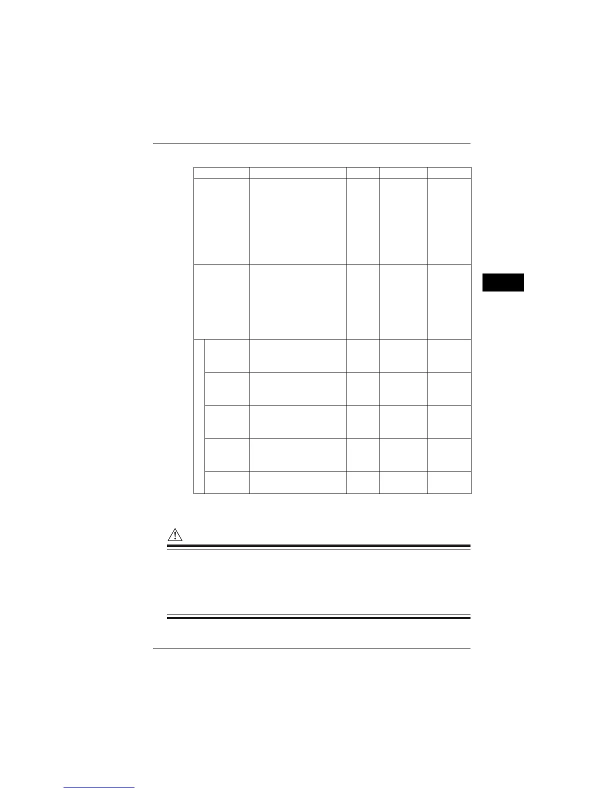
● Setting Information of Analog Output Items
Item Element Order Magnification Output Rate
NORMAL
Voltage (U1, U2, U3, Uave)
Current (I1, I2, I3, I4, Iave)
Power (P)
Reactive power (Q)
Apparent power (S)
Power factor (PF)
Phase angle (PA)
Frequency (F)
_
_
_
_
_
_
_
_
_
_
_
_
__
_
E. ENERGY
LEVEL
Voltage (U1, U2, U3)
Current (I1, I2, I3, I4)
Power (P)
1 to 50
1, 10, and
100 times
CONTENT
Voltage (U1, U2, U3)
Current (I1, I2, I3, I4)
Power (P)
1 to 50
1, 10, and
100 times
HARM. PA
Voltage (U1, U2, U3)
Current (I1, I2, I3, I4)
Power (P)
1 to 50
TOTAL VAL
Voltage (U1, U2, U3)
Current (I1, I2, I3, I4)
Power (P)
THD
Voltage (U1, U2, U3)
Current (I1, I2, I3, I4)
Active energy (Wh+)
Regenerative energy (Wh-)
Lagging reactive energy (Varh+)
Leading reactive energy (Varh-)
1V/1kWh
1V/5kWh
1V/10kWh
1V/50kWh
1V/100kWh
1V/500kWh
1V/1000kWh
Harmonics
NOTE
• Analog output items that can be set vary depending on the wiring.
• For measurement of multiple loads, analog output items can be selected on a
load basis. A number representing load(s) is appended following each ele-
ment (e.g., I1_1, I1_2, P_1, and P_2).
• For Scott connections, a symbol representing which load is applied is ap-
pended following each element (e.g., U1_3P, U1_1P, P_3P, and P_1P).
6.9 Analog I/O Settings

 Loading...


