4-3
IM DLM5058-03EN
External Signal I/O
4
Note
During synchronous operation, triggers are generated only from the trigger output terminal of the main unit.
They are not generated from the sub unit.
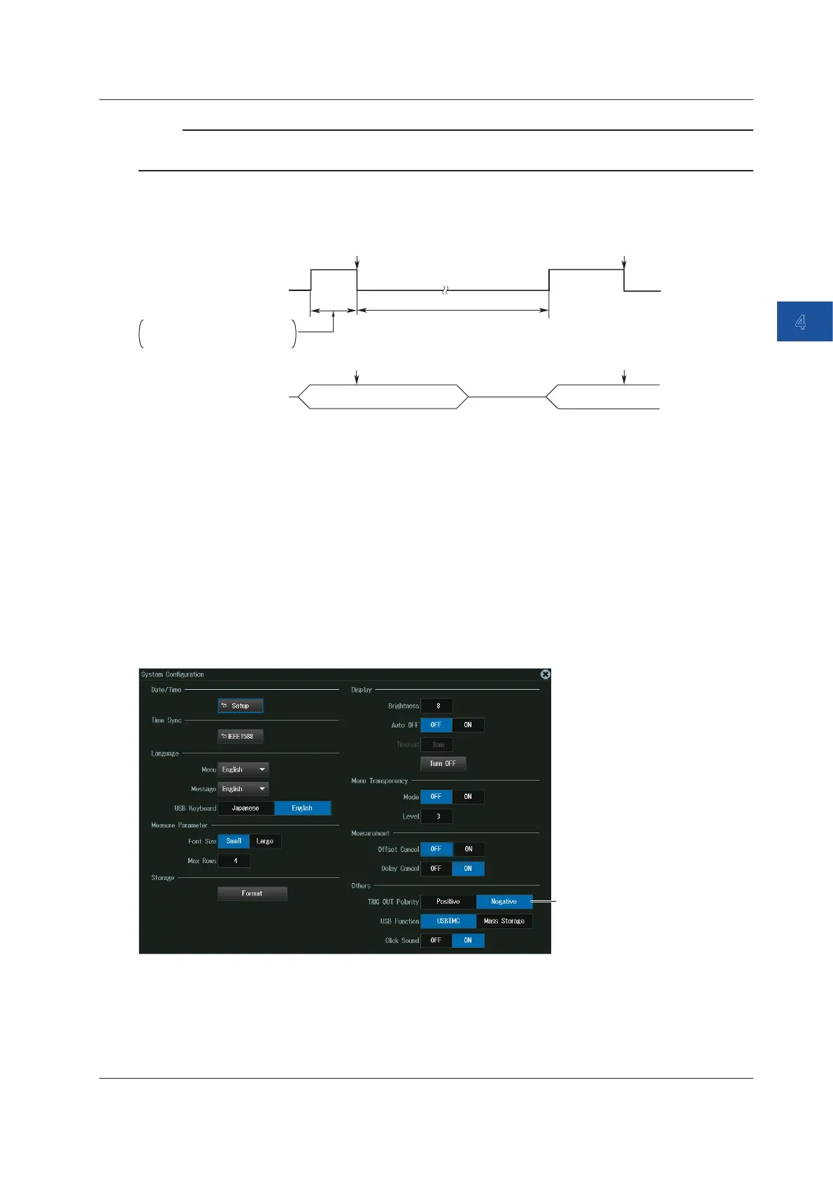
Low Level and High Level Hold Times
High
Low
Trigger output
(negative logic)
3
(Post-trigger time + internal
processing time)
Trigger occurrence
Trigger occurrence
Pre
Trigger Trigger
PostPost Pre
Waveform acquisition
Pre-trigger time +
internal processing time
2
1
1 High (high level)
3
period: The sum of the pre-trigger time and the internal processing time. The
minimum period is 50 ns.
2 Low (low level)
3
period: The sum of the post-trigger time and the internal processing time. The
minimum period is 500 ns. The minimum period is 500 ns.
3 When you select positive logic, the definitions of high and low given here are reversed.
Setting the Output Logic (TRIG OUT Polarity)
You can set the output logic for the signal transmitted from the trigger output terminal.
UTILITY System Configuration Menu
Press UTILITY and then the System Configuration soft key. The following menu appears.
4.2 Trigger Output (TRIGGER OUT)

 Loading...


