2-11
IM DLM5058-03EN
Measurement Preparation
2
2.4 Connecting Probes
WARNING
• When connecting a device under measurement to the instrument, be sure to turn off the
device. It is extremely dangerous to connect or disconnect a measuring lead while the
device under measurement is on.
• Do not apply input voltage exceeding the maximum input voltage, withstand voltage, or
allowable surge voltage.
• To avoid electric shock, be sure to ground the instrument. Furthermore, connect the ground
of the probes or input connectors to the ground potential of the device under measurement.
The ground of each signal input terminal (input connector) of this instrument is common
with the instrument’s protective ground (see the block diagram in appendix 3). Do not
apply floating potential signals to the input connector ground. This is extremely dangerous
as doing so will cause a short to the ground potential. Use a differential probe when
measuring floating potential.
• Avoid continuous connection in an environment where a surge voltage may occur.
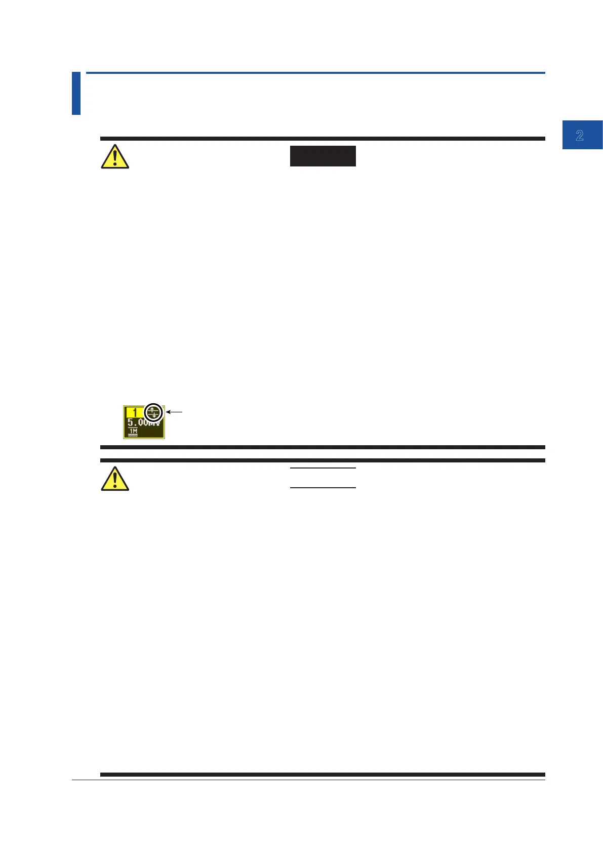
• If over-range is indicated, the instrument may be receiving a voltage higher than the
observed waveform or measured waveform values. To prevent electric shock, change
the vertical scale with the SCALE knob so that the entire amplitude of the waveform is
displayed within the waveform display area, and check the input voltage level.
Over-range indication
CAUTION
• The probe interface terminals are located near the input terminals on this instrument. Do
not short the probe interface terminals. When you connect a probe, make sure to prevent
an excessive voltage caused by static electricity, etc., from being applied to the probe
interface terminal, as this may damage the terminal.
• The maximum input voltage for 1 MΩ input is 300 Vrms or 400 Vpeak when the frequency
is 100 kHz or less. Applying a voltage greater than either of these limits may damage the
input section. If the frequency is above 100 kHz, damage may occur even when the voltage
is below this value.
• The maximum input voltage for 50 Ω input is 5 Vrms or 10 Vpeak. Applying a voltage
greater than either of these limits may damage the input section.
• If the input coupling is AC, in accordance with the frequency response, the input signal
is attenuated more in lower frequencies.* As such, even when a high voltage signal is
received, the over-range indicator (see “WARNING” provided earlier) may not be displayed
on the instrument’s screen. As necessary, switch the input coupling to DC to check the
input signal voltage.
* For details, see section 1.1, “Input Coupling,” in the User’s Manual, IM DLM5058-02EN.
• If you change the input coupling setting* while waveform acquisition is stopped, the input
coupling on the instrument is actually changed when waveform acquisition is executed the
next time. Be careful of the maximum input voltage.
• For information about how to handle a probe, refer to the user's manual that came with the
probe.

 Loading...


