1-1
IM DLM5058-03EN
1
Component Names and Functions
Chapter 1 Component Names and Functions
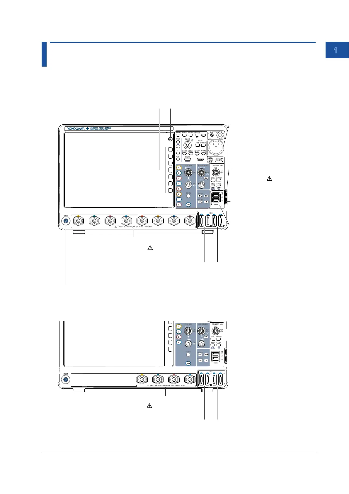
1.1 Front, Right, Left, Top, and Rear Panels
Front Panel
DLM5038 and DLM5058
Functional ground terminal
When correcting a probe phase,
connect the probe’s ground wire to this
terminal.
Signal output terminal for probe
compensation adjustment
(1 kHz/1 Vp-p)
Transmits phase compensation signals
for probes.
Phase correction procedure → sec. 2.5
LCD
Description of the displayed
contents → sec. 1.3
Use this key to clear soft key menus and pop-up menus.
Jog shuttle
Use the jog shuttle to change values
and move cursors.
Turn the shuttle ring to vary the rate at
which values change. The rate is set
according to the shuttle ring angle.
Use these keys to select items on the setup
menus that appear during configuration.
USB ports for peripherals
Use to connect a USB keyboard, USB
mouse, USB storage device, or USB
printer.
USB keyboard or mouse → sec. 3.4
USB storage device or printer
→ see the user’s manual
Keys and knobs → sec. 1.2
LOGIC C and D (logic signal input ports)*
Connect logic probe to these ports to observe up
to 32-bit logic signals. → sec. 2.6
LOGIC A and B (logic signal input ports)
Connect logic probe to these ports to observe up to 16-bit
logic signals. → sec. 2.6
* LOGIC C and D (logic signal input ports) are equipped on models with the /L32 option.
Signal input terminals - probe interface
terminals (CH1 to CH8)
Connect probes to these terminals to observe
analog signals. → sec. 2.4
DLM5034 and DLM5054
LOGIC C and D (logic signal input ports)*
Connect logic probe to these ports to observe up
to 32-bit logic signals. → sec. 2.6
LOGIC A and B (logic signal input ports)
Connect logic probe to these ports to observe up to 16-bit
logic signals. → sec. 2.6
* LOGIC C and D (logic signal input ports) are equipped on models with the /L32 option.
Signal input terminals - probe interface
terminals (CH1 to CH4)
Connect probes to these terminals to observe
analog signals. → sec. 2.4

 Loading...


