4-6
IM DLM5058-03EN
4.4 GO/NO-GO Signal Output (GO/NO-GO)
Signal Output Port
The connector uses an RJ-12 modular jack. Use a cable designed for GO/NO-GO determination,
such as optional accessory 366973.
Pinout
The pin arrangement is as follows.
6
1
1
Pin No. Signal Name Logic
2
3
4
5
6
NC (no connection)
NC (no connection)
GO OUT
NO-GO OUT
Connector on
Negative logic
Negative logic
GND
NC (no connection)
Output Signal
NO-GO OUT Signal
When the determination result is NO-GO, the output signal level (the TTL level) temporarily
changes from high level (H) to low level (L).
GO OUT Signal
When the determination result is GO, the output signal level (the TTL level) temporarily changes
from high level (H) to low level (L).
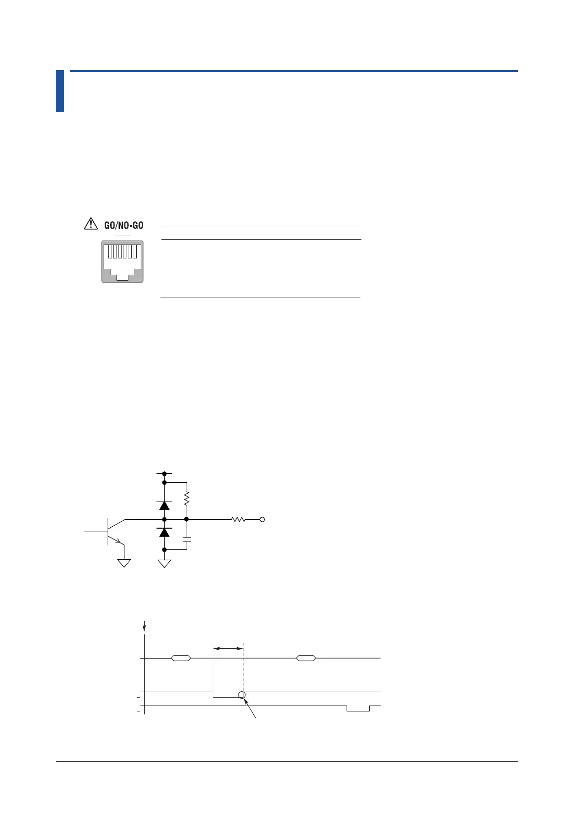
Signal Output Circuit Diagram
GO OUT
NO-
100 Ω
4.7 kΩ
100 pF
Output Timing
EXEC
10 ms
or more
Waveform
acquisition
Waveform
acquisition
Judgment
Judgment
Result Result
GO OUT
The signal remains low until the instrument is ready to accept the next measurement.
If you have specified an action to perform when conditions are true, this time is
extended until that action is complete.

 Loading...


