1-12
IM DLM5058-03EN
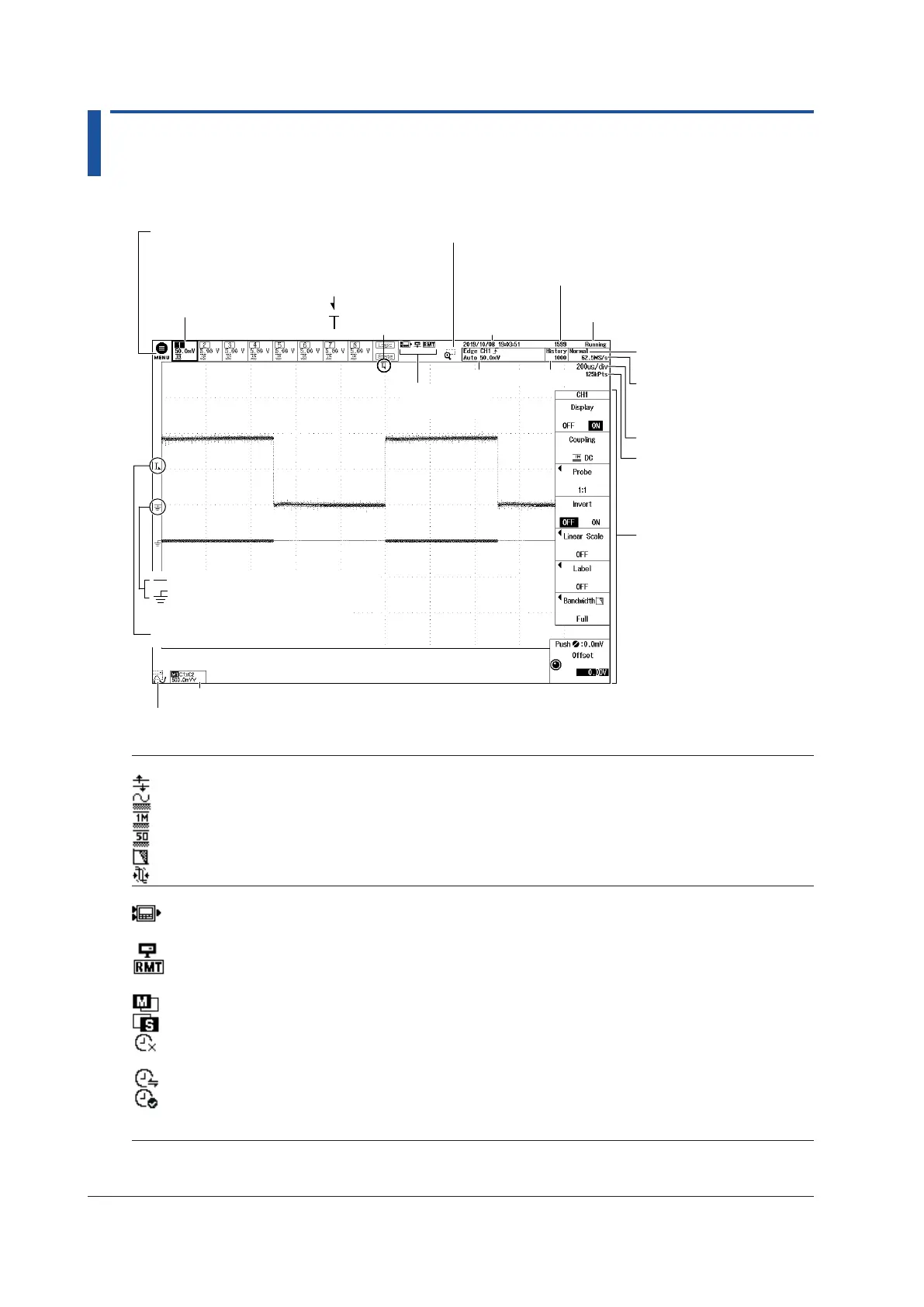
1.3 Screens
Normal Analog Signal Waveform Screen
Acquisition mode
Time/div
Waveform acquisition state
Sampling mode
and sample rate
Trigger position
Number of waveform acquisitions
Trigger level mark
Ground level mark
The display is inverted when Invert is set to ON.
Vertical position mark
Channel information
See the next table.
Trigger
information
Trigger point
See the next table.
Displays the top menu
→ sec. 3.2
Set the range and zoom the waveform → sec. 3.2
History
Math/Ref vertical scale
See the next table.
Turns transparent display on or off
Displays operation screens (setup menus and dialog boxes) transparently
Date and time
Setup menu
Icon
See the next table.
See the next table.
See the next table.
Channel Information
Appears when over-range is occurring
Appears when the input coupling is set to AC
Appears when the input coupling is set to DC
Appears when the input coupling is set to DC50
Appears when the bandwidth limit is not set to Full
Appears when the probe’s deskew value is not set to 0.00 ns
Icon
Analysis, such as automated measurement of waveform parameters, serial bus analysis, or
user-defined computation, in progress
Connected to an FTP server
In remote mode. Key operations are locked.
For details, see the Communication Interface User’s Manual, IM DLM5058-17EN.
Running as the main unit of synchronous operation
Running as the sub unit of synchronous operation
Not communicating with the master. The sampling clock is running based on the internal
oscillator.
Starting to synchronize with the master and adjusting the time and sampling clock.
Established synchronization with the master and the time and sampling clock are stable. To
measure using the IEEE 1588 time synchronization feature, start measuring after this icon is
displayed.

 Loading...


