START-UP
Axiovert 200 Interfaces ... / Microscope and power supply ... Carl Zeiss
B 40-080 e 03/01 2-19
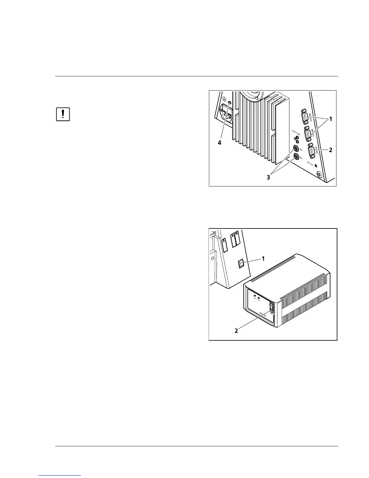
2.9 Interfaces of the Axiovert 200 M
Prior to connecting any components,
switch off the microscope.
The Axiovert 200 M is connected to a PC via the
RS 232 interface (2-23/2).
Motorized components of the Axiovert 200 M
(e.g. the motorized condenser) are connected via
the SB interfaces (2-23/3).
Further external control components (e.g. the 3-
axis motor control MCU 28 of the scanning stage)
must be connected to the CAN/SB connectors
(2-23/1).
2.10 Switch microscope and ebq 100 dc
power supply on and off
• Switch the microscope on and off using the line
switch (2-24/1).
• If a fluorescence illuminator (e.g. N HBO 103) is
connected (see section 2.13.3, "Attachment of
illuminator N HBO 103"), switch power supply
ebq 100 dc on and off via the line switch
(2-24/2).
2.11 Equipotential bonding terminals
Terminals for equipotential bonding for
electrophysiological measurements are located on
the rear side of the stand (2-23/4) and on the
underside of the binocular tubes (000000-1005-
827 and 000000-1005-828).
Connection to the stand is by 4mm banana plugs.
The connectors on the tubes are provided with M4
internal thread.
Fig. 2-23 Axiovert 200 M (rear)
Fig. 2-24 Power supply ebq 100 dc (front)