START-UP
Carl Zeiss Attachment of transmitted-light illumination Axiovert 200
2-8 B 40-080 e 03/01
2.3 Attachment of transmitted-light
illumination
2.3.1 Attachment of carrier for trans-
mitted-light illumination (100 W)
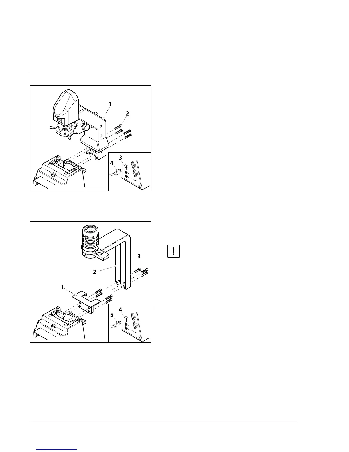
• Attach carrier (2-5/1) to the relevant contact
surface on the rear of the stand and use the
SW 4 Allen key to tighten the four enclosed
hexagonal screws (2-5/2).
• Connect plug (2-5/4) for the LCD display (if
available) to the SB socket (2-5/3) at the
instrument rear.
Alignment of the carrier (100 W) is not required.
2.3.2 Attachment of carrier for trans-
mitted-light illumination (30 W)
Before attachment of the carrier for
transmitted-light illumination 30 W
(451380-0000-000) to the stand, the
control electronics included in the
stand must be changed by Zeiss
service staff.
• Remove the HAL 100 and N HBO 103
illuminators from the microscope.
• If required, remove carrier (100 W) by
loosening the four hexagonal screws (SW 4)
and disconnect plug of the LCD display from
the SB socket.
• Screw adapter plate (000000-1005-842, 2-6/1)
onto the contact surface on the stand rear
using the four hexagonal screws.
• Attach centering pin of the carrier for transmitted-light illumination (30 W) (2-6/2) to the adapter
plate and tighten the three SW 4 hexagonal screws (2-6/3).
Alignment of the carrier (30 W) is not required.
• Connect power supply plug of the carrier for transmitted-light illumination 30 W (2-6/5) to the
12 V / 100 W connector (2-6/4) on the rear of the stand.
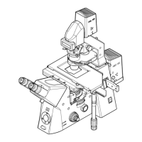
Fig. 2-5 Attachment of carrier for trans-
mitted-light illumination (100 W)
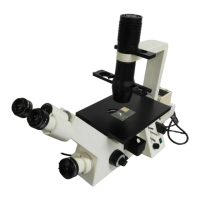
Fig. 2-6 Attachment of carrier for trans-
mitted-light illumination (30 W)