START-UP
Carl Zeiss Attachment of microscope stages Axiovert 200
2-10 B 40-080 e 03/01
2.5 Attachment of microscope stages
2.5.1 Attachment of mechanical stage
130x85 R/L and mounting frame
for mechanical stage (K)
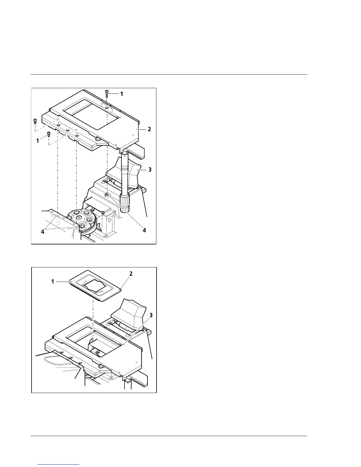
The mechanical stage is mounted to the stand
directly above three contact points with the
relevant drilled holes.
• To improve access during stage assembly, the
carrier (2-8/3) for transmitted-light illumination
can be tilted backwards.
• Place mechanical stage (2-8/2) on the three
contact points (2-8/4) of the stand and fix it in
position using three hexagonal screws (2-8/1)
(two at the front, one at the rear).
Three countersunk holes each on the front and
rear of the mechanical stage 130x85 R/L permit
attachment with the drive knobs being positioned
on the right or on the left.
• Then insert the mounting frame (K) (2-9/1) into
the mechanical stage.
For this purpose, position the red dot (2-9/2) of
the corner of the mounting frame on the red
dot of the mechanical stage (2-9/3) and press
the mounting frame diagonally against the
springs and downwards into the recess. Make
sure that the mounting frame is seated
correctly.
2.5.2 Attachment of scanning stage
• The scanning stage is attached in the same way
as the mechanical stage. However, the three
spacers (4 mm) enclosed with the stand must
be inserted before attachment of the scanning
stage.
• The cable to the separate motor control unit
must then be connected.
Fig. 2-8 Attachment of mechanical stage
130x85
Fig. 2-9 Insertion of mounting frame (K)