40
Safety, Installation and Operations Manual – Translation of original instructions
When three phase pumps are being commissioned for the first time, and also when used on a new site, the direction of rotation of the impeller
must be checked by a qualified technician.
The pump carries a decal which indicates the correct impeller rotation direction (green arrow) and the relative kickback direction (red arrow).
When the pump is viewed from above (motor cover), the impeller must rotate CLOCKWISE.
Proceed as follows:
1. Take the safety precautions detailed in the manual.
2. Place the pump vertical on its feet or base.
3. Secure the pump by tying a suitably sized chain or sling to the handle on the top to prevent it from falling over after the kickback.
4. Temporarily connect the yellow-green wire to the system ground connector and then connect the power supply wires to the contactor.
5. Make sure there are no people or objects within a distance of at least 2 metres of the pump.
6. Operate the start switch, power up the pump for a few seconds and then shut off the power by flicking the stop switch.
7. Check that the rotation direction is correct.
If the pump is rotating in the wrong direction, invert two of the pump’s three power supply phases and try again, repeating the procedure described.
Once the connection which provides the correct rotation direction has been obtained, MARK the precise order in which the wires have been con-
nected to the system, DISCONNECT the power supply wires from the pump and proceed with definitive installation.
EN 1092-2 Tab.8
(PN10-16)
ANSI B16, 1-89
Tab.5
Undrilled
EN 1092-2 Tab.8
(PN10-16)
ANSI B16, 1-89
Tab.5
Undrilled
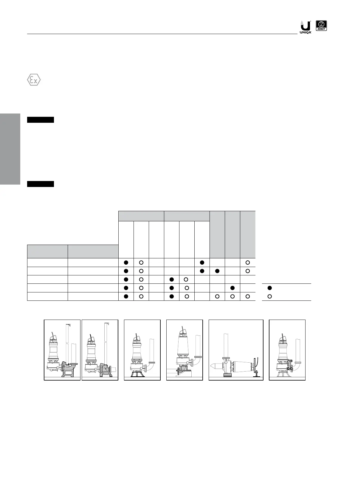
P DAC-V / DAC-H
S KBS
KBC
*
KBS-H
Standard
-
Optional
* Possible holes for non Zenit accessories
(For the mounting holes required, refer to the product technical sheet)
EN
DAC KBS KBC FLXKBS-H
 Loading...