41
Safety, Installation and Operations Manual – Translation of original instructions
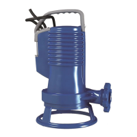
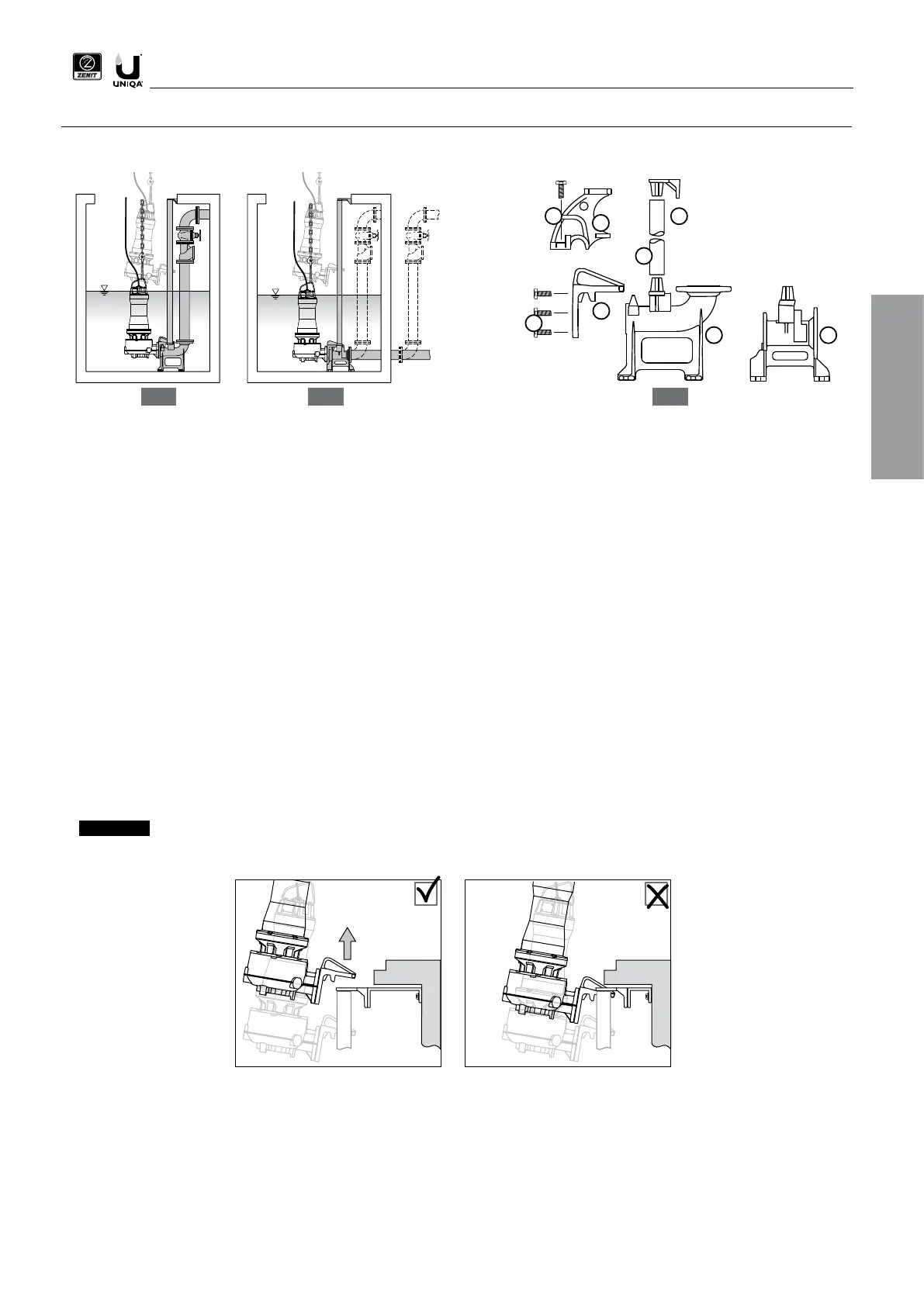
1a. DAC V coupling device (vertical outlet)
1b. DAC H coupling device (horizontal outlet)
2. Coupling flange or hook (changes depending on pump model)
3. Screws
4. Pipe guides (not included)
5. Spacer bracket
1. Check that the pump is disconnected from the power supply panel and the impeller turns in the correct direction
2. Fix the flange to the pump’s outlet port with the screws provided. For models with hooks, fix the hook to the pump body using the screws
provided.
3. Place the coupling device on the bottom of the tank and mark the position of the holes required to fix it.
4. Make holes of suitable diameter for the coupling device fixing slots and secure it firmly to the bottom of the tank using chemical or expansion
plugs.
5. Use stainless steel metal fasteners or protect the screws and nuts with a suitable product to prevent corrosion.
6. Connect the outlet pipeline to the coupling device. A shut-off valve and a ball type check valve with full free passage should be installed using
a connection pipe with length equal to at least 5 times the diameter of the outlet.
7. Fit the pipe guides, cut to the correct length, to the coupling device. Galvanised steel pipes, or preferably stainless steel pipes, of suitable
diameter can be used (see technical information).
8. Connect the spacer bracket to the top end of the pipe guide and mark the positions of the holes required to fix it to one of the sides of the tank;
make sure that the pipe guides are perfectly vertical with the aid of a plumb-line or a spirit-level.
With this type of installation , the pump can be removed from and replaced in the tank quickly without any work on the system.
9. Make holes of suitable diameter for the spacer bracket fixing slots and secure it firmly using chemical or expansion plugs. Protect the screws
and nuts with a suitable product to prevent corrosion.
10. Clean the tank to remove any remaining debris and waste.
11. Secure a chain or sling of suitable size to the handle and lower the pump into the tank, sliding the flange along the pipe guides until it reaches
the coupling device.
12. Secure the electric cables so that they cannot be twisted or torn or drawn in by the pump.
13. Bring the cables out of the tank through a clean, smooth duct. Do not lay cables with tight bends or in positions with risk of crushing or damage.
14. Connect the electric cables to the control panel
EN
3
1a 1b
4
2
5
3
2
7
 Loading...