111
Achieving Motorola/GE DC Control Currents
Achieving Motorola/GE DC Control Currents
Normally, the available positive and negative currents which are based on 2.5 mA
increments will achieve proper control of DC Remote Controlled base stations. However,
a feature on the late DC Dual Channel Cards allow the exact Motorola and GE currents to
be achieved. This is done using the Console Programming System for Windows (CPSW)
custom DC programming in the System Configuration menu, and switches on the back of
the DCC (requires the DC Remote Daughter Board to be installed on the applicable
channel).
If the “A” channel of a Dual Channel Card needs Motorola/GE standard currents, close
option switch 6 of the card's configuration switch. If the “B” channel of the Dual Channel
Card needs Motorola/GE standard currents, close option switch 2 of the card's
configuration switch.
Then using CPSW, locate the System Configuration menu and program all channels that
require the standard Motorola/GE currents with a Channel Type of DC Control... and a
DC Control Protocol of Custom (see Channel Configuration on page 85). Then using the
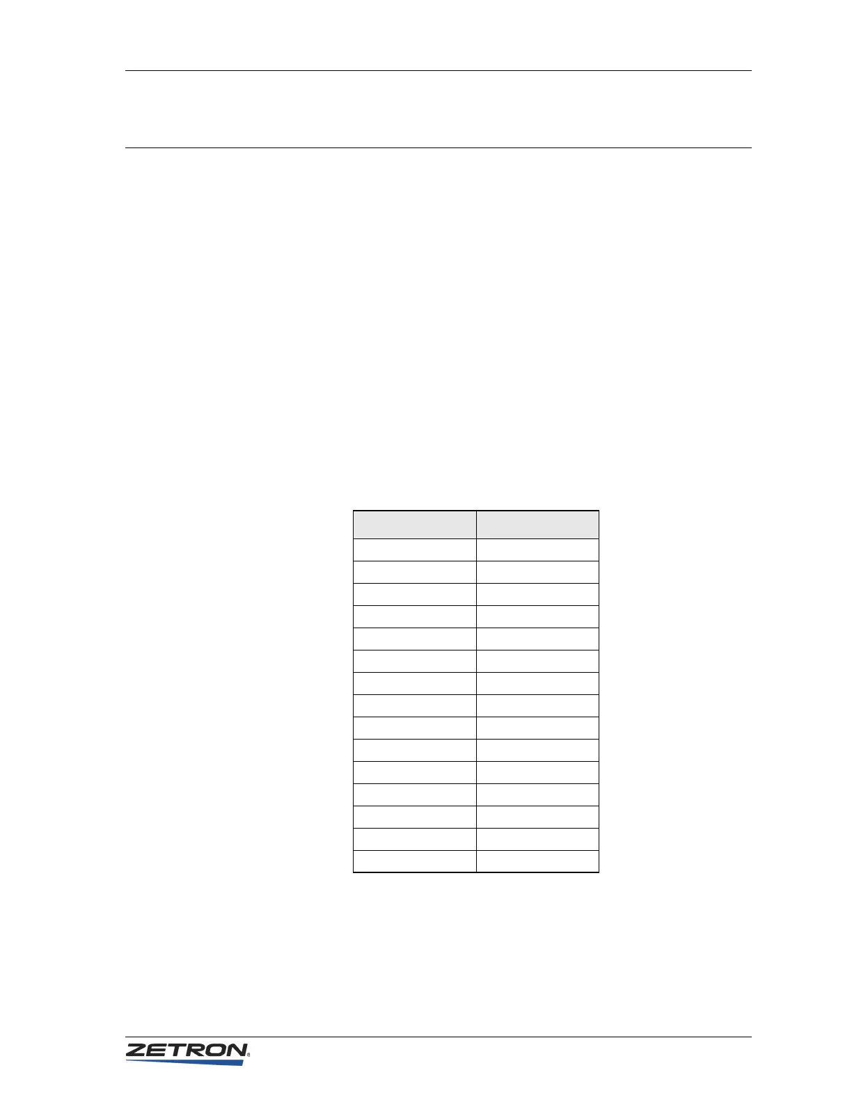
conversion table below, locate the desired current and find the CPSW current to use for
DC Control Current.
Desired Current CPSW Current
0.0 mA +0.0mA
+2.5 mA +2.5 mA
+5.5 mA +5.0 mA
+6.0 mA +7.5 mA
+11.0 mA +10.0 mA
+12.5 mA +12.5 mA
+15.0 mA +15.0 mA
+15.5 mA +15.5 mA
-2.5 mA -2.5 mA
-5.5 mA -5.0 mA
-6.0 mA -7.5 mA
-11.0 mA -10.0 mA
-12.5 mA -12.5 mA
-15.0 mA -15.0 mA
-15.5 mA -15.5 mA


 To Next Page