33
Wiring to the Channels
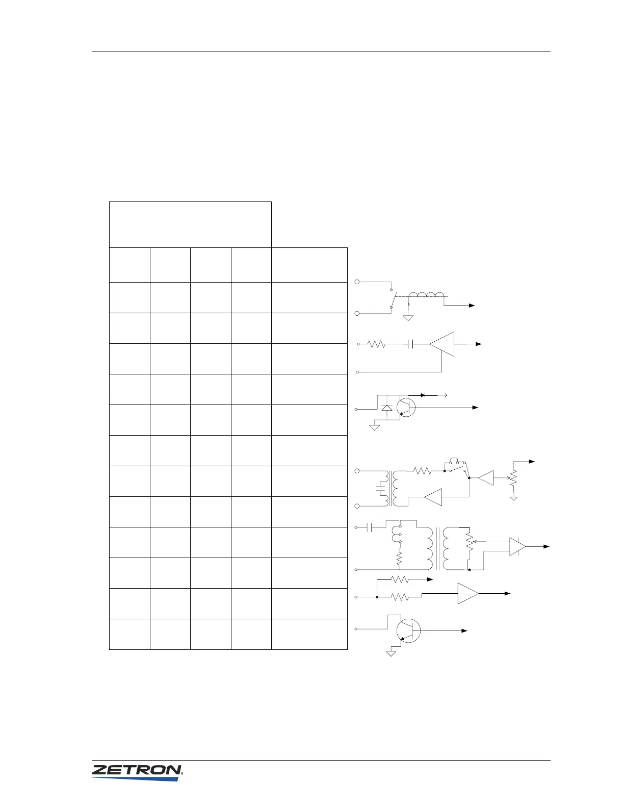
Equivalent Circuits
The figures accompanying Table 6 illustrate the interface signals’ equivalent circuits and
the plug connections on which they may be found. All pin numbers listed in the following
table refer to the 50-pin connectors on the rear of the unit and correspond to the terminal
numbering on the punch-down blocks.
Table 6: Equivalent Circuits for Console I/O
Table 7 summarizes the signals found on each channel plug. The table also contains the
wire colors for the 25-pair cables often used to connect to the plugs.
2.2uF
600 Ohm
600 Ohm
10K Ohm
2.2 uF
10K Ohm
3.3K Ohm
10K Ohm
+12V
+12V
600 Ohm
10 uF
50-Pin Connector Pin Numbers
J2, J3, and J4
Ch-A Ch-B Ch-C Ch-D Signal
1 7 13 19 PTT +
26 32 38 44 PTT –
2 8 14 20 Record
27 33 39 45 Analog Ground
3 9 15 21 Aux Output
28 gnd 34 v+ 40 gnd 46 v+ Ground or V+
4 10 16 22 Tx Audio +
29 35 41 47 Tx Audio –
5 11 17 23 Rx Audio +
30 36 42 48 Rx Audio –
6 12 18 24 Busy Input
31 37 43 49 Busy Output