57
Model 4010 Auxiliary I/O Card
Table 14: Auxiliary Output Configuration Jumpers
Auxiliary Inputs
The inputs are single ended logic level inputs. Only a contact closure to ground is required
to activate the interface. The inputs are protected against voltage levels higher than the 5 V
interface level.
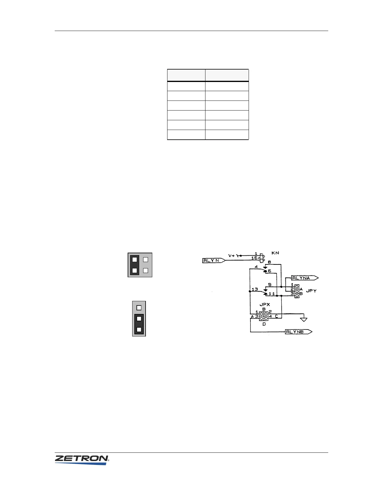
Auxiliary Output Jumper Settings
Each relay output has two sets of jumpers, as shown in Figure 9.
Figure 9: Auxiliary Output Relay Jumpers
By arranging these jumpers, each relay output can be used as described in Table 15.
Output # Jumpers
Output 1 JP1 and JP7
Output 2 JP4 and JP10
Output 3 JP6 and JP12
Output 4 JP2 and JP8
Output 5 JP3 and JP9
Output 6 JP5 and JP11
Typical Relay Diagram
A
D
C
B
A
B
Jumper Pairs As Viewed
On Board Near Relays
 Loading...