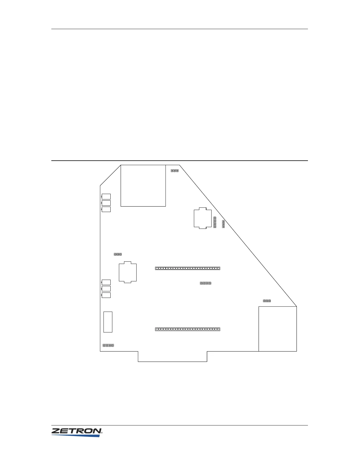
Model 4010 Dual Channel Card Layout
103
Appendix A: Model 4010 Components
Model 4010 Dual Channel Card Layout
On older boards, P1 and JP6 may be located in different positions than shown here. P2 and
P3 are used to mount daughterboard such as the LOTL or Channel ANI Decoders.
For a list of jumpers and switches, see Table 4 on page 27. For a list of potentiometers, test
points, and audio adjustment information, see Receive Audio Adjustment on page 42 and
Transmit Audio Adjustment on page 45.
JP7
JP4
JP2
JP1
JP3
B
A
B
AB
AB
AB
SW1
CA
JP6
B
CA
1
2
3
4
5
6
7
8
R52
R53
R54
R9
R10
R11
P1
P2
126
P3
126
Model 4010 (P/N 702-9377)
 Loading...

