Console Installation
20 025-9227S
wire is recommended. Strip the ends of the wire back 0.25 inches and insert into J16 and
secure by screwing down the terminal. The pin connections are as follows:
System Grounding
Proper earth grounding is an important electrical consideration. The earth ground protects
the system and personnel from lightning strikes, provides a path for any electrostatic
discharge (ESD), and provides a solid reference for the system. Improper grounding of the
system could cause susceptibility to ESD, induced noise from input power wiring, and
reduced effectiveness of lightning protection devices. Induced noise could cause false
signal indications or a variety of system errors.
A “star” grounding system (a single point ground to which satellite grounds are
connected) is the best grounding system. The central star point must be firmly attached to
a low-impedance earth ground point, such as a ground rod.
If protective punch-down blocks are used, a large diameter (6-gauge) copper conductor (or
equivalent braided strap/ bus bar) must be connected between the ground lug of each block
and the earth ground or central star grounding point. With the protected punch-down
blocks, it is best to wire directly to the earth ground if possible. Each piece of equipment
should have its chassis grounded to the central star point with a separate ground wire. The
gauge of the wire depends on the length of the run, 12 gauge is adequate if the length is
less than 15 feet. The length of the runs should be minimized. Securely connect a
grounding wire to the case of each unit making sure that a metal-to-metal connection is
made (no paint or oxidation layer). Most Zetron equipment provides a grounding stud.
Figure 5 shows a central star grounding system.
All earth grounds in the system should be isolated from signal lines. It is easy to couple
ESD or lightning noise spikes if these lines run parallel for any distance. The AC power
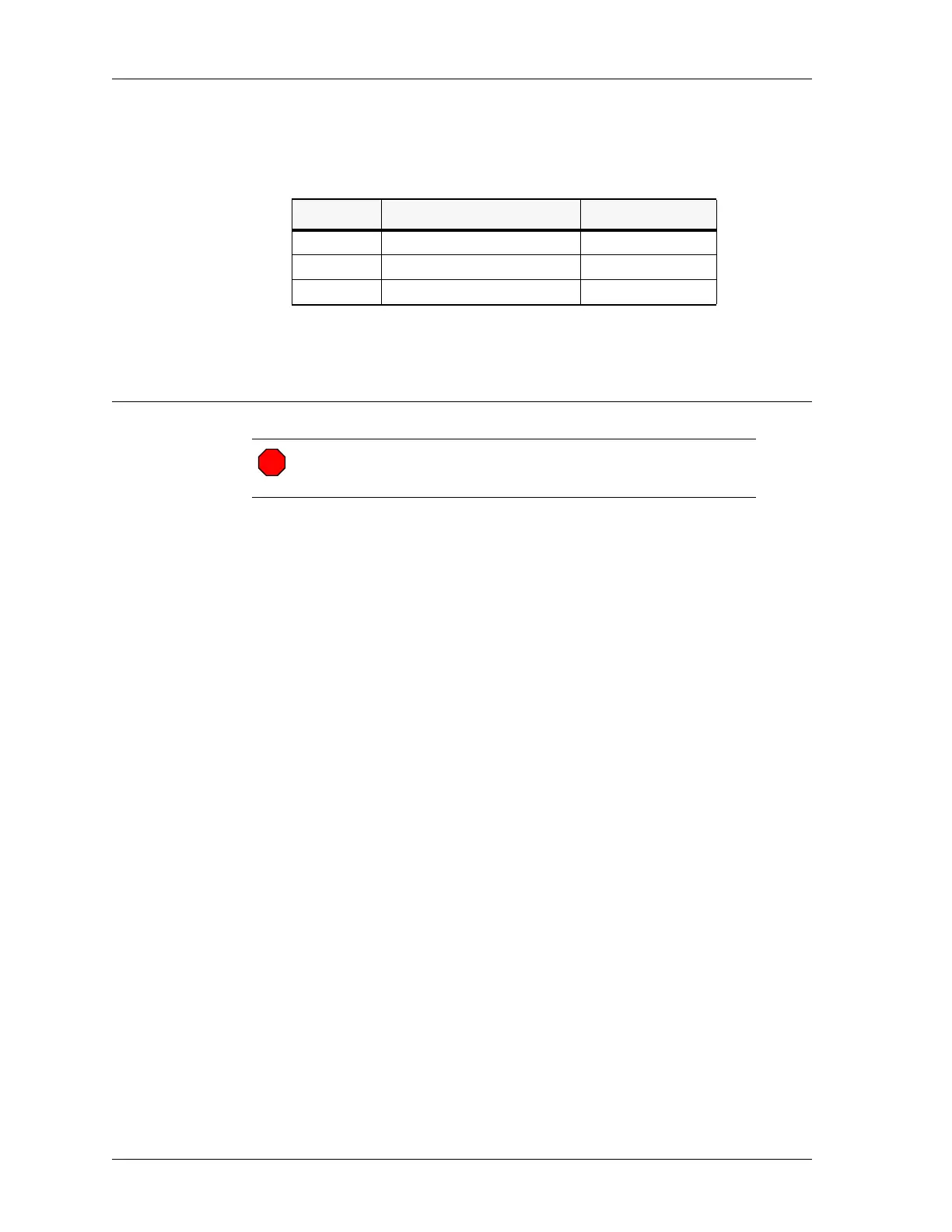
J16 PIN Location SIGNAL
1 Nearest to channel card slot PWR+
2 Center terminal PWR-
3 Nearest to side of case PWR-
Warning! Improper system grounding can cause electric shock to
personnel, damage to equipment, and system malfunctions.
STOP
 Loading...