37
Inputs and Outputs
Inputs and Outputs
The main board of the Model 4010 is equipped with eight inputs and outputs. These inputs
and outputs can be used as auxiliary I/O, or as spare I/O. All inputs on the board must be
one or the other (auxiliary or spare). All outputs must be one or the other (auxiliary or
spare). By default, the I/O is set to spare inputs and outputs. See Input/Output
Configuration on page 90 for an explanation of the differences between auxiliary and
spare I/O.
Auxiliary I/O can be added by installing Auxiliary I/O Cards (see Model 4010 Auxiliary I/
O Card on page 56). Each Auxiliary I/O Card adds six auxiliary inputs and six auxiliary
outputs. There is no method for adding spare inputs or spare outputs.
Inputs
The Console has eight inputs, which are a standard feature and located on the Control
Board (as are the outputs below). Inputs are programmed through CPSW (see Input/
Output Configuration on page 90). Inputs are TTL compatible (0 to 5 V
DC
only) and
accessible through the wiring access hole in the rear of the unit and wired to P8. The
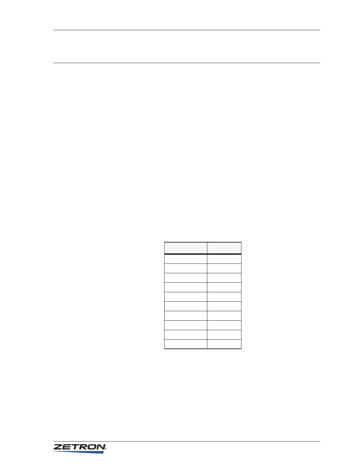
mating connector is provided with the unit. The pinout is shown in Table 8.
Table 8: P8 Inputs
Signal P8 Pin #
INPUT 1 1
INPUT 2 2
INPUT 3 3
INPUT 4 4
INPUT 5 5
INPUT 6 6
INPUT 7 7
INPUT 8 8
(open) 9
GROUND 10