Console Installation
28 025-9227S
Line Termination
The transmit audio output and receive audio input may be configured for low-impedance
or high-impedance. For systems with only one control point on a channel, the channel
should be configured for low-impedance (600 Ω). For systems with multiple control
points on a channel, all but one parallel-connected channel should be configured for high-
impedance. One control point in a multiple control point system should be configured for
low-impedance termination, and this should be the channel card at the far end of the
transmission line from the base station.
Low-impedance configurations present a 600Ω impedance on the transmit and receive
lines at all times. High-impedance configurations present a 3500Ω (or greater) impedance
on the transmit/2-wire receive line while idle, and 600Ω while transmitting. On the 4-wire
receive line, high-impedance is 10,000Ω at all times.
Busy Transmit Inhibit
Each channel may be configured to either allow or inhibit transmission on a Busy channel.
A channel is Busy whenever its cross-busy input (Busy In) is activated by a locally
paralleled control point, or when its line-operated transmit light (LOTL) is activated by a
remotely paralleled control point. Usually inhibiting while busy is desired to prevent
confused communications and to keep proper line terminations and levels. However, when
line conditions cause falsing of the LOTL, it is desirable to be able to transmit even while
busy.
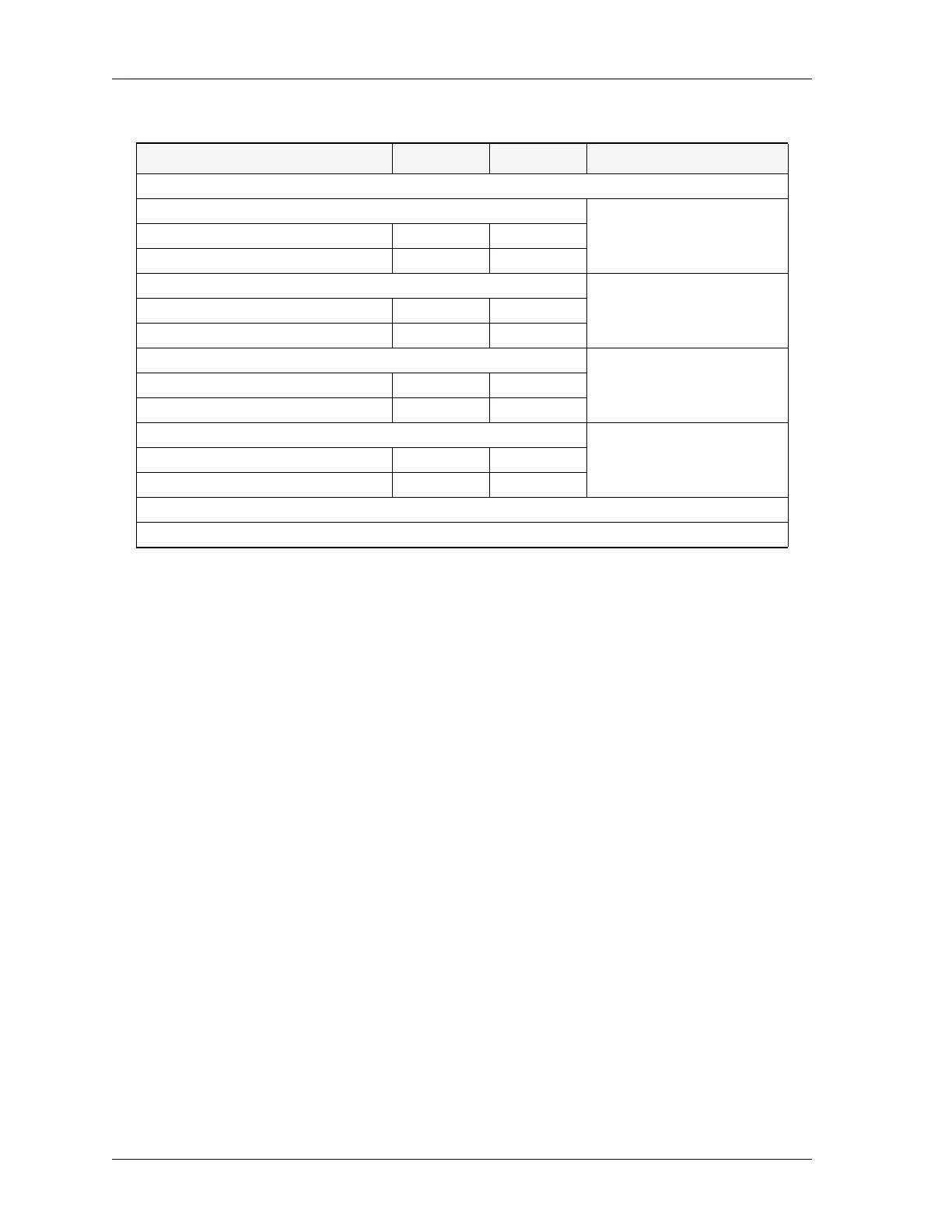
Option Switch (OPT) - function depends on type of channel
Tone Co nt ro l
See Tone Control, HLGT
Duration on page 29.
Standard HLGT Duration SW1-3-OFF SW1-7-OFF
Custom HLGT Duration SW1-3-ON SW1-7-ON
DC Current Control
See DC Current Control —
Current Selection on page
29.
Zetron standard levels SW1-3-OFF SW1-7-OFF
Motorola/GE currents SW1-3-ON SW1-7-ON
Full Duplex (FD)
See Full Duplex on page 29.FD disabled SW1-4-OFF SW1-8-OFF
FD enabled SW1-4-ON SW1-8-ON
LOTL
See LOTL Disable on page
29.
LOTL enabled JP1-A * N/A
LOTL disabled JP1-B * N/A
* JP1 in this instance refers to jumper JP1 on the daughter board, not the Dual Channel Card.
Jumpers JP5 and JP8 are fixed in place and should not be changed.
Option Name Channel A Channel B Notes