Console Installation
24 025-9227S
Configuring Dispatch Consoles
The console has several jumper selectable configuration options. Table 2 shows the
various options and the normal factory setting. See Model 4010 Dual Channel Card
Layout on page 103 for the location of these jumpers.
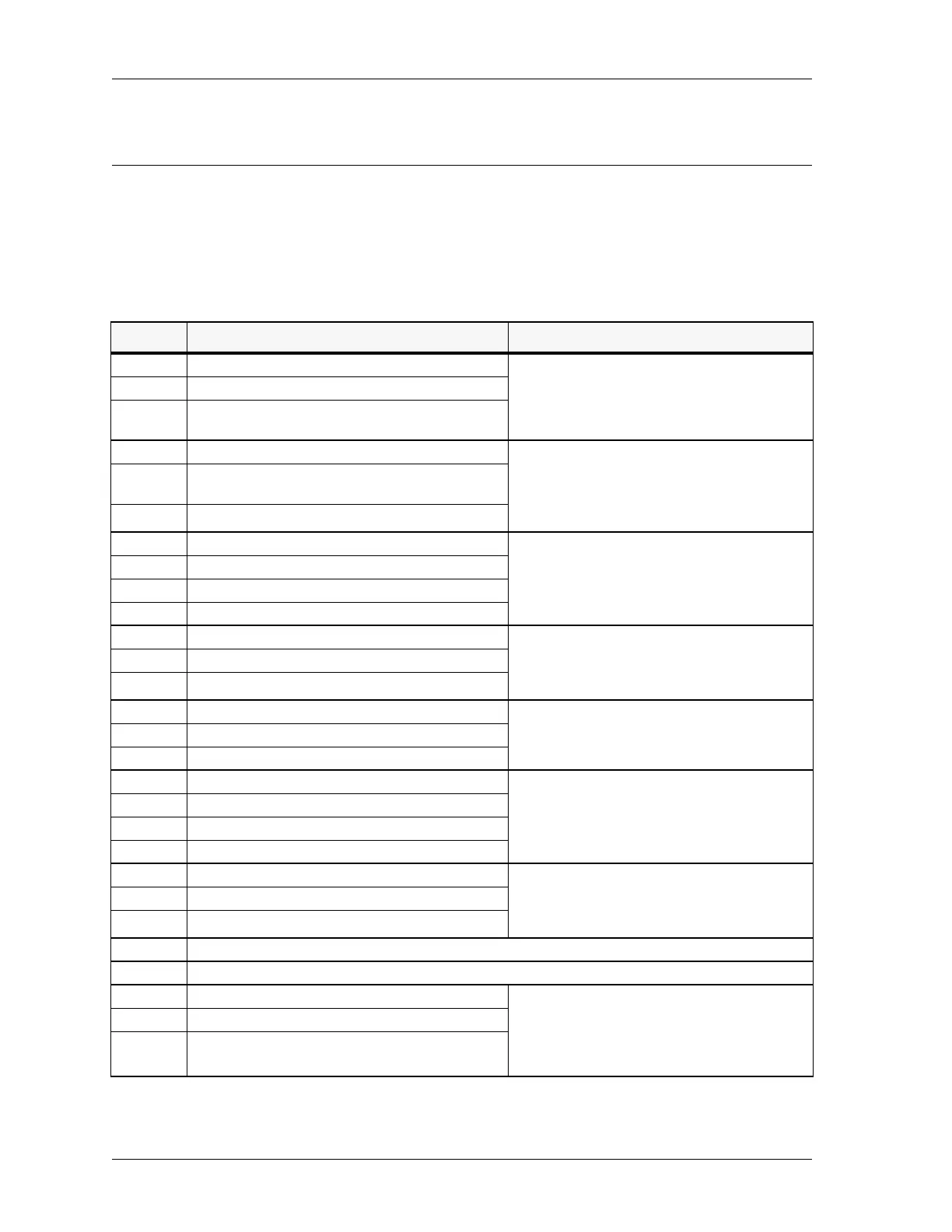
Table 2: Model 4010 Control Board Jumpers and Switches
Jumper Options Notes
JP1 Recorder Output & VU meter The audio recorder output and the VU meter
include the console microphone transmit audio and
its Select receive audio. Place the jumper in
position B to add Unselect receive audio as well.
A* Unselect audio not sent to Recorder/VU
B Unselect audio mixed with Select audio to Recorder
Output and VU
JP2 Auxiliary Audio to Select Audio The transmitted audio from the auxiliary audio
input may be monitored with the Select speaker.
For example, when an external encoder is used, the
operator can hear the encoder tones as they are
being transmitted.
A* Auxiliary audio mixed with Select audio on Select
speaker
B Auxiliary audio disabled
JP3 Unselect Speaker / Headset & Handset Audio Determines where Unselect audio is heard. You
might want to change this if, for example, you want
the Unselect speaker to turn off when the software
detects a handset lifted from a cradle or a headset
plugged into a jack.
A* Unselect audio always on unselect speaker
B Unselect audio switch under software control
C Unselect audio always on headset/handset
JP4 Headset/Handset Unselect Monitor Occasionally, it is desirable to monitor both Select
and Unselect audio on the earpiece of the headset
or handset. Jumper JP4 may be used to enable the
Unselect audio monitoring.
A* Unselect audio not heard at headset/handset
B Unselect audio heard at headset/handset
JP5 Auxiliary Audio input impedance If an external encoder is used, use JP5 to set the
input impedance of the Model 4010 to match the
output impedance of the encoder.
A* Auxiliary Audio 600 Ω impedance
B Auxiliary Audio 10 kΩ impedance
JP6 Select Speaker / Headset & Handset audio Determines where Select audio is heard. You might
want to change this. For example if you want the
Select speaker to turn off when the software detects
a handset lifted from a cradle or a headset plugged
into a jack.
A Select audio always on select speaker
B* Select audio switch under software control
C Select audio always on headset/handset
JP7 Tone generator input filter The output of the tone generator has an additional
high frequency filter that can be inserted. This
filter is not required, in which case the jumper
should be left in position A.
A* No tone filter
B Tone filter connected
JP8 Reserved for use with the TRHI. See Telephone/Radio Headset Interface on page 53.
JP9 Not used.
JP10 Operator Paging/Alert/Warning Audio Operator audio refers to the paging and alert/
warning tones generated by the M4010. These
tones can be irritating when monitored by the
dispatcher, depending on where it is heard and how
loud it is. The level is adjusted by R104.
A* Operator Audio to Select Speaker
B Operator Audio to Unselect Speaker
 Loading...