806834 v1.02 07.21 G5 Online install instructions and user guide
17
SAFETY
INSTALLATION
TROUBLE
SHOOTING
COMMISSION
USER GUIDE
TAP SAFETY
LCD SCREEN
CONTACT
INSTALLATION
GUIDE
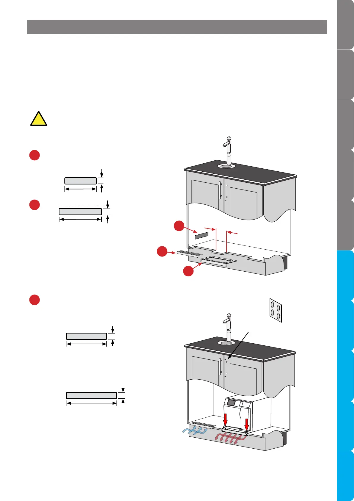
Section 2 Ventilation
4mm door buffers
(supplied)
Air inlet cut-out options (refer to the
instructions provided with the vent grilles)
Air exhaust vent cut-out.
Check size relative to your product.
2.3 Models with front vent (BCS20, BCS30 & BCS Home; BC20, BC30 & BC Home, C40, CS
Home, C Home; B60, B100, BA60, BA100, B Home, BA Home)
The cupboard exhaust must be cut out. It provides a safe exhaust for refrigerant gas
in the unlikely event of a leak.
• Cold air is drawn in through the inlet vent and gap provided by the door buffers.
• The inlet vent is positioned in the cupboard side, door or floor.
• Warm air is exhausted through the base of the Command Centre, through the cupboard floor cut-out.
• Observe 100mm inlet / outlet vent separation.
c
c
b
a
b
a
285
60
100mm
326
43max
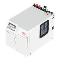
• Align the mounting plate to the edge of the
cupboard floor, and secure with the 2 self-
tapping screws supplied.
• Then, secure Command Centre to mounting
plate with 2 screws supplied.
300
40
For Command Centre width 339mm
240
40
For Command Centre width 280mm