Home
Zte
Switch
ZXR10 8900 Series
Hardware Installation Manual
Page 13 (Chapter 1 Safety Instructions)
Zte ZXR10 8900 Series - Chapter 1 Safety Instructions; Safety Introduction; Safety Description
109 pages
Manual
To Next Page
To Next Page
To Previous Page
To Previous Page
Loading...
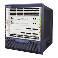
Chapter
2
Equipment
Installation
F
IGURE
3
S
IDE
E
LEVATION
OF
ZXR10
8908
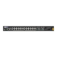
The
side
elev
ation
of
ZXR10
8905
with
six
slots
is
shown
in
Figure
4
.
F
IGURE
4
S
IDE
E
LEVATION
OF
ZXR10
8905
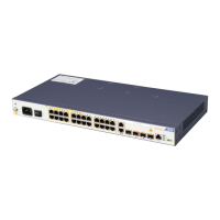
The
front
panel
view
of
ZXR10
8902
is
shown
in
.
Condential
and
Proprietary
Information
of
ZTE
CORPORA
TION
5
12
14
Table of Contents
Main Page
Default Chapter
3
Table of Contents
3
About this Manual
7
Safety Description
9
Safety Introduction
9
Table 2 Safety Description
9
Equipment Installation
11
Installation Content
11
Figure 1 ZXR10 8900 Installation Diagram
11
Equipment Component
12
Figure 2 Side Elevation of ZXR10 8912
12
Figure 3 Side Elevation of ZXR10 8908
13
Figure 4 Side Elevation of ZXR10 8905
13
Equipment Installation Flow
14
Figure 5 Front Panel View of ZXR10 8902
14
Table 3 Basic Parameters
14
Figure 6 Equipment Installation Flow
15
Chapter 3 Installationpreparation Tableofcontents
17
Figure 7 NOC Room Layout
17
Installation Preparation
17
NOC Room Inspection
17
Indoor Environment of NOC Room Inspection
18
Table 4 Temperature and Humidity Requirements
20
Auxiliary Equipment Inspection
21
Grounding Inspection
21
Power Supply Requirements Inspection
21
Required Tools
22
Technical Document Preparation
23
19" Standard Cabinet Installation
25
Bottom of Cabinet Installation
25
Cabinet Position Rule
25
Cabinet Base Installation Preparation
26
Introduction to Cabinet Base Installation
26
Adjustable Base Installation Mode
27
Adjustable Base Selection
27
Figure 8 Adjustable Base Installation Flow
27
Installation Flow
27
Figure 10 Adjustable Base: Model B
28
Figure 11 Adjustable Base: Model C
28
Figure 9 Adjustable Base: Model a
28
Figure 12 Adjustable Base Installation Diagram
29
Figure 13 Adjustable Base Structure Diagram (Model B)
29
Figure 14 Position of Single Cabinet Installation
30
Positioning Adjustable Base
30
Figure 15 Positions of Dual Cabinet Installation
31
Table 5 Adjustable Base Installation Mark Size (MM)
31
Installing Adjustable Base
32
Figure 16 Adjustable Base Height Diagram
33
Table 6 Adjustable Base Adjust Height Diagram
33
Figure 17 Fixation of Adjustable Base
34
Installation of Base Directly on Floor
35
Figure 18 Adjustable Shims
35
Figure 19 Single Cabinet Base Installation Diagram
35
Installation Flow of Base Directly on Floor
35
Figure 20 Installation Flow of Base Directly on Floor
36
Installing Base on Floor Directly
36
Figure 21 Position Single Cabinet Installation
37
Figure 22 Position Dual Cabinet Installation
37
Table 7 Installing the Base Directly Marking Size
38
Installation of Fixed Base Mode
39
Figure 23 Single Cabinet Expansion Bolt Installation Diagram
39
Installation Flow of Fixed Base Mode
39
Design of Fixed Base
40
Figure 24 Installation Flow of Fixed Base
40
Figure 25 19D8H20 Single Cabinet Drill Installation Diagram
41
Figure 26 19D8H20 Dual Cabinet Drill Installation Diagram
41
Figure 27 19D8H20 Single Cabinet Fixed Base Diagram
42
Positioning Fixed Base
42
Figure 28 19D8H20 Single Cabinet Installation Diagram
43
Table 8 Fixed Base Installation Marking Size (MM)
43
Figure 29 Installation of Base
44
Installing Fixed Base
44
Cabinet Installation
45
Cabinet Installation Requirements
45
Cabinet Installation Preparation
45
Cabinet Installation Flow
46
Cabinet Installation Mode
47
Figure 30 Cabinet Installation Flow Diagram
47
Installing Cabinet by Adjustable Base
47
Figure 31 Remove Truckles
48
Figure 32 Footing Structure
48
Figure 33 Fix Cabinet
49
Figure 34 Pressure Pad and Insulated Rubber Pad
49
Figure 35 the Clearance between Panel Wood and Floor
50
Installing Cabinet on Floor Directly
50
Figure 36 Cabinet Base Is Installed on Floor Directly
51
Figure 37 Remove Truckles
52
Installing Cabinet by Fixed Base
52
Figure 38 Footing Structure
53
Figure 39 Fix Cabinet by Pressure Plate
54
Figure 40 Remove Truckles
55
Figure 41 Fix the Cabinet by Bolt
56
Connecting the Cabinets
57
Figure 42 Remove Screw of Angle Support
57
Figure 43 Remove the Angle Support
57
Figure 44 Reinstallation the Angle Support
58
Figure 45 Connection between Two Near Cabinets
58
Cabinet Accessories Remove and Installation
59
Remove and Installation of Front and Back Doors
59
Installing Front and Back Doors
59
Removing Front and Back Doors
59
Installation and Clean of Dustproof Mesh
60
Figure 46 Door Installation Diagram
60
Figure 47 Positions of Dustproof Plug-In Box
61
Installing and Cleaning Dustproof Plug-In Box
61
Figure 48 Outstructure Dustproof Plug-In Box Diagram
62
Figure 49 Simple Dustproof Meshes
62
Installing and Cleaning Dustproof Mesh
62
Installing Panel Wood
63
Figure 50 Plastic Dustproof
63
Figure 51 Fix Front and Back Panel Wood
64
Figure 52 Installation of Front and Back Panel Wood Diagram
64
Installing Top Panel and Top Inside Panel
65
Figure 53 Fix Side Panel Wood Diagram
65
Figure 54 Installation of Single Cabinet Panel Wood Diagram
65
Figure 55 Top Panel Installation Diagram
66
Figure 56 Top Inside Panel Installation Diagram
67
Installing Power Supply Cable and Grounding Cable
68
Figure 57 Installation of All Top Panel and Top Inside Panel on Dual Cabinet
68
Master Device Installation
73
Installing Plug-In Box
73
Figure 60 Floating Nut Installation
74
Plugging and Unplugging Card
75
Figure 61 Installation of Subrack
75
Figure 62 Card Structure
76
Figure 63 Plugging Card Step 2
77
Figure 64 Plugging Card Step 3
77
Installation of Power Supply Module
78
Figure 65 Plugging Card Step 5
78
Installing Power Supply Module of ZXR10
78
Figure 66 Plugging Power Module Step 1 (ZXR10 8908)
79
Figure 67 Plugging Power Module Step 2 (ZXR10 8908)
80
Figure 68 Plugging Power Module Step 3 (ZXR10 8908)
80
Figure 69 Fake Power Supply Module
81
Figure 70 Install and Remove Fake Power Supply Module
82
Installing Power Supply Module of ZXR10 8902
82
Figure 71 Plugging Power Module of ZXR10 8902 Step 1
83
Figure 72 Plugging Power Module of ZXR10 8902 Step 3
83
Installation of Fan Plug-In Box
84
Figure 73 Plugging Fan Plug-In Box Step 1
84
Installing Fan Plug-In Box of ZXR10
84
Figure 74 Plugging Fan Plug-In Box Step 2
85
Installing Fan Plug-In Box of ZXR10 8902
85
Figure 75 Plugging Fan Plug-In Box of ZXR10 8902 Step 1
86
Figure 76 Plugging Fan Plug-In Box of ZXR10 8902 Step 2
86
Installation of Cabling Rack
87
Installing Vertical Supporter
87
Figure 77 Install Vertical Supporter in Cabinet
88
Figure 78 Install Vertical Supporter in Working Table
89
Installing Horizontal Cable Plate
89
Figure 79 Horizontal Cable Plate Installation
90
Power Supply Cables Installation
91
DC Power Supply Cable
91
Table 9 Power Cable and Grounding Wires
91
AC Power Supply Cable
92
Figure 80 DC Distribution System Grounding
92
Grounding Wire Installation
93
Figure 81 AC Distribution System Grounding
93
Grounding Wire Interconnection between Cabinets
93
Grounding Wire Interconnection Inside the Cabinet
93
Plug-In Box Protection Grounding Wire Installation
94
Installation Notice
94
Chapter 7 Externalcable Installation Tableofcontents
95
External Cable Types
95
Control Console Cable Installation
95
Network Cable Installation
96
Figure 82 Control Console Cable
96
Figure 83 Network Cable with RJ45 Connectors
96
Table 10 Connections of Control Console Cable
96
Fiber Installation
97
Table 11 Straight-Through Network Cable RJ45 Connections
97
Table 12 Crossover Network Cable RJ45J Connections
97
Label Types
98
Table 13 Fiber Terminal Forms
98
Figure 85 Roll-Up Self-Mulching Laser Print Type II Labels
99
Figure 86 Schematic Diagram of a Power Cable Label
100
Figure 87 Pasting Position of Power Cable Labels
100
Figure 88 Structure of Optical Fiber
101
Figure 89 Meaning of Optical Fiber
101
Figure 90 Structure of Coaxial Cable Label
102
Figure 91 Meaning of Coaxial Cable Label
102
Figure 92 Horizontal Model-I Label in English
102
External Cable Installation
95
Hardware Installation Inspection
103
Cabinet Inspection
103
Power Supply Cable Inspection
104
Cabling Inspection
104
Label Inspection
104
Figures
105
Tables
109
Other manuals for Zte ZXR10 8900 Series
User Manual
186 pages
Command Reference
147 pages
Command Manual
177 pages
Hardware Manual
131 pages
Instructions
14 pages
Related product manuals
Zte ZXR10 8900E series
132 pages
Zte ZXR10 2928
341 pages
Zte ZXR10 2918E
266 pages
Zte ZXR10 2952E
266 pages
Zte ZXR10 3928A
51 pages
Zte ZXR10 2910E-PS
266 pages
Zte ZXR10 2918E-PS
266 pages
Zte ZXR10 5250-28TC
708 pages
Zte ZXR10 5900 Series
208 pages
Zte ZXR10 5250 Series
708 pages
Zte ZXR10 2900E Series
750 pages
Zte ZXR10 5900E Series
149 pages
 Loading...