MES-3728 User’s Guide
43
CHAPTER 3
Hardware Overview
This chapter describes the front panel and rear panel of the Switch and shows you how to
make the hardware connections.
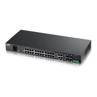
3.1 Front Panel
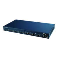
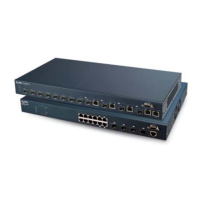
The following figure shows the front panel of the Switch.
Figure 9 Front Panel: AC/DC Model
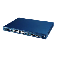
Figure 10 Front Panel: AC Model
Ethernet Ports
Dual Personality Interfaces
Console Port
Management Port
LEDs
ALARM slot
Power Connection
Mini-GBIC slots
Ethernet Ports
Console Port
Management Port
LEDs
ALARM slot
Power Connection Dual Personality Interfaces
Mini-GBIC slots
 Loading...