Chapter 3 Hardware Overview
MES-3728 User’s Guide
50
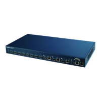
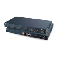
3.2 Rear Panel
The following figure shows the rear panel of the Switch. The rear panel contains a connector
for external backup power supply.
Figure 20 Rear Panel
3.2.1 External Backup Power Supply Connector
The Switch supports external backup power supply (BPS).
The backup power supply constantly monitors the status of the internal power supply. The
backup power supply automatically provides power to the Switch in the event of a power
failure. Once the Switch receives power from the backup power supply, it will not
automatically switch back to using the internal power supply even when the power is resumed.
3.3 LEDs
After you connect the power to the Switch, view the LEDs to ensure proper functioning of the
Switch and as an aid in troubleshooting.
Table 2 LED Descriptions
LED COLOR STATUS DESCRIPTION
BPS Green On The backup power supply is connected and active.
Blinking The system is receiving power from the backup power supply.
Off The backup power supply is not ready or not active.
PWR Green On The system is turned on.
Off The system is off.
SYS Green On The system is on and functioning properly.
Blinking The system is rebooting and performing self-diagnostic tests.
Off The power is off or the system is not ready/malfunctioning.
ALM Red On A hardware failure is detected, or an external alarm is active.
Off The system is functioning normally.
Ethernet Ports
LNK/ACT Green Blinking The system is transmitting/receiving to/from a 10 Mbps Ethernet
network.
On The link to a 10 Mbps Ethernet network is up.
Amber Blinking The system is transmitting/receiving to/from a 100 Mbps Ethernet
network.
On The link to a 100 Mbps Ethernet network is up.
Off The link to an Ethernet network is down.
Mini-GBIC Slots
 Loading...