30
Fig. 99
Fig. 103
Fig. 104
Fig. 100
Fig. 101 Fig. 102
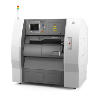
Fig. 98
3. Touch the ‘Clockwise’ and ‘Counter-clockwise’ buttons to automatically
move the carriage around the corners of the print area. (Fig. 98)
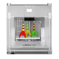
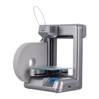
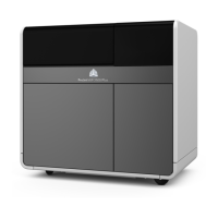
4. From the side of the printer, observe any changes
in distance between the Print Plate and the Print Jet
during each movement along the side of the Print
Plate. (Fig. 99-102)
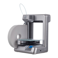
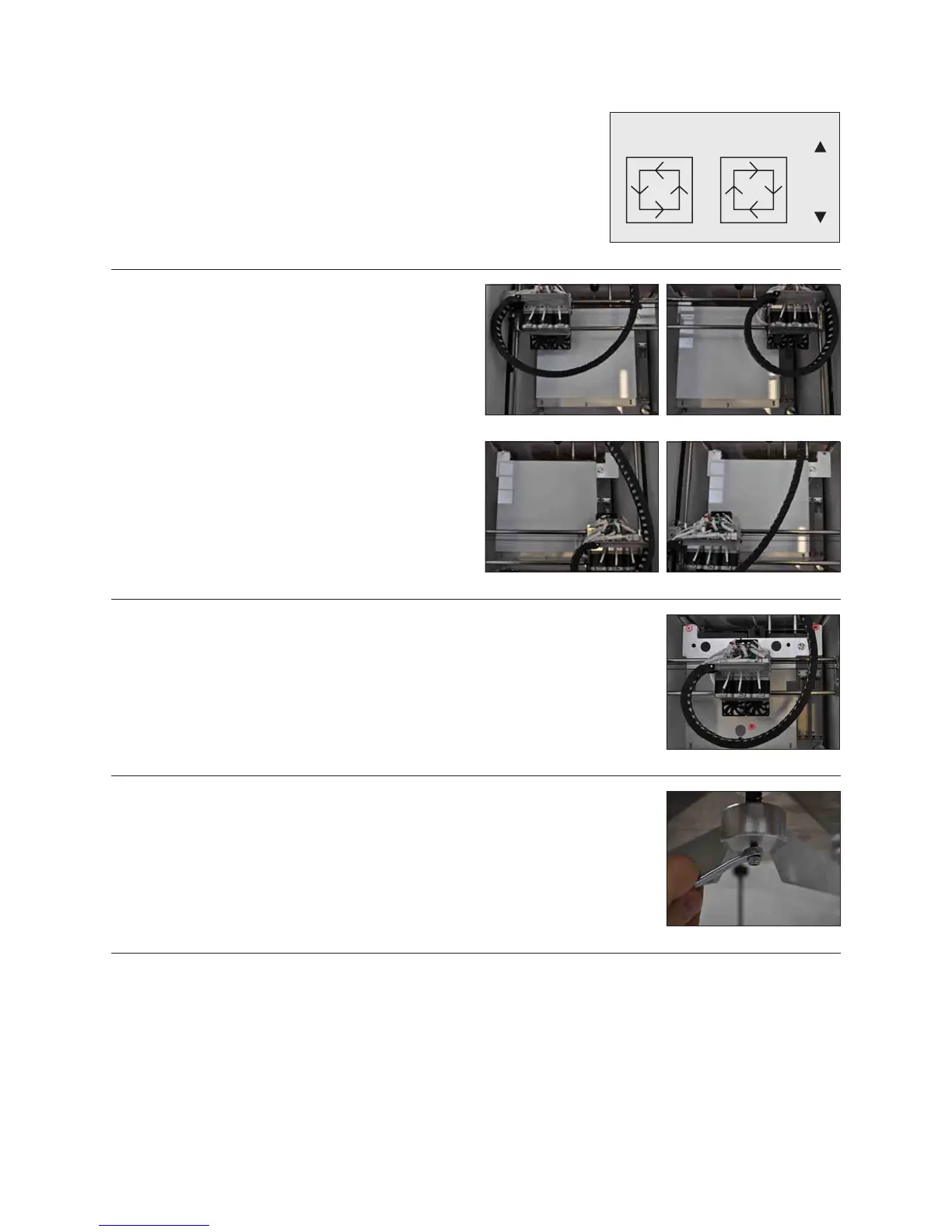
5. Using the 3mm hex driver from the tool kit, adjust the height of the Print Pad bolts
(Fig. 103) to make each side level.
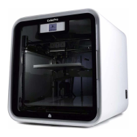
6. There is a locking nut beneath each of the 3 bed bolts that must be loosened
with the 8mm spanner wrench before the bolt can be adjusted. (Fig. 104)
7. It may take several Print Jet movements and bolt adjustments to ensure that the
Print Plate is level.
8. Ensure that axes have been checked from the appropriate side of the printer (to better gauge atness).
LEVEL BED