46
VCCX2 Controller Technical Guide
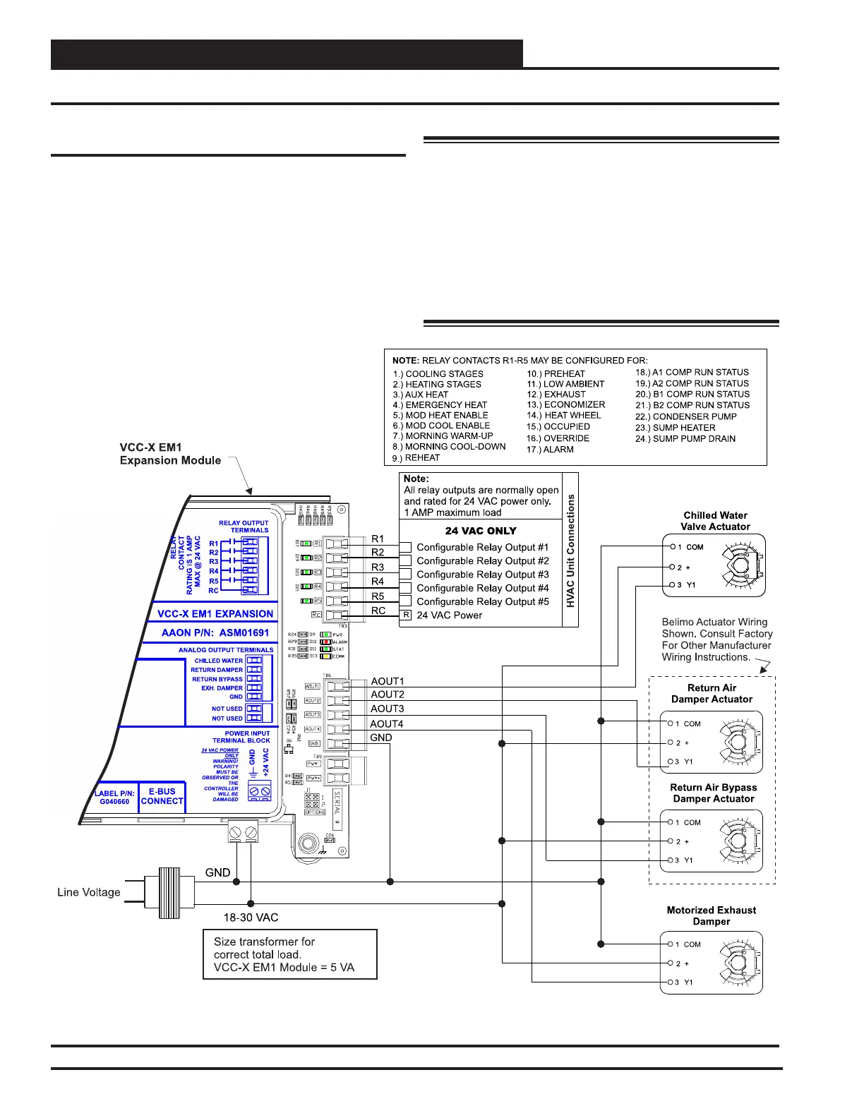
VCC-X EM1 Expansion Module Outputs
The VCC-X EM1 Expansion Module must be connected to 24
VAC as shown in the wiring diagram below. Please see Table
1, page 24 for correct VA requirements to use when sizing the
transformer(s) used for powering the expansion module.
Also, please note that when wiring the VCC-X EM1 Expansion
Module, its contacts must be wired as wet contacts (connected
to 24 VAC).
See Figure 27, this page for input wiring.
WARNING: Observe Polarity! All boards must be
wired with GND-to-GND and 24VAC-to-
24VAC. Failure to observe polarity will
result in damage to one or more of the
boards. Expansion modules must be wired
in such a way that the expansion modules
and the controller are always powered
together. Loss of power to the expansion
module will cause the controller to become
inoperative until power is restored to the
expansion module.
(for Return Plenum Pressure
Control Applications)
Figure 27: VCC-X EM1 Expansion Module Output Wiring Diagram
WIRING
VCC-X EM1 Expansion Module Outputs