47
VCCX2 Controller Technical Guide
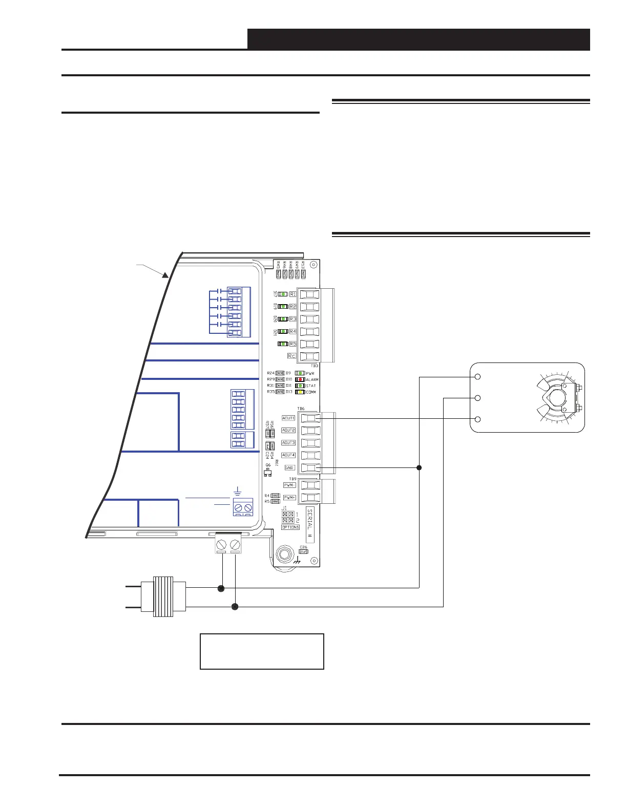
Modulating Cooling Output
This output is used to control a Modulating Chilled Water Valve
to maintain the Cooling Supply Air Temperature Setpoint. The
output is congured for 2-10 VDC direct acting operation. See
Figure 28, this page for wiring details.
+24 VA C
GND
RELAY
CONTACT
RATING IS 1AMP
MAX @ 24 VA C
R1
R2
R3
R4
R5
RELAYOUTPUT
TERMINALS
ANALOG OUTPUT TERMINALS
GND
NOT USED
NOT USED
RETURN DAMPER
RETURN BYPASS
CHILLED WATER
NOT USED
E-BUS
CONNECT
24 VAC POWER
ONLY
WARNING!
POLARITY
POWER INPUT
TERMINAL BLOCK
VCC-X E EXPANSIONM1
AAON P/N: ASM01691
LABELP/N:
G040660
RC
2+
Y13
COM1
VCC-X EM1
pansion Module
AOUT1
18-30 VAC
GND
Line Voltage
GND
Chilled Water
Valve Actuator
VCC-X E1 Module = 5 VAm
correct total load.
Size transformer for
Figure 28: Chilled Water Valve Actuator Wiring Diagram
WARNING: Observe Polarity! All boards must be
wired with GND-to-GND and 24VAC-to-
24VAC. Failure to observe polarity will
result in damage to one or more of the
boards. Expansion modules must be wired
in such a way that the expansion modules
and the controller are always powered
together. Loss of power to the expansion
module will cause the controller to become
inoperative until power is restored to the
expansion module.
WIRING
Chilled Water Valve Actuator