61
VCCX2 Controller Technical Guide
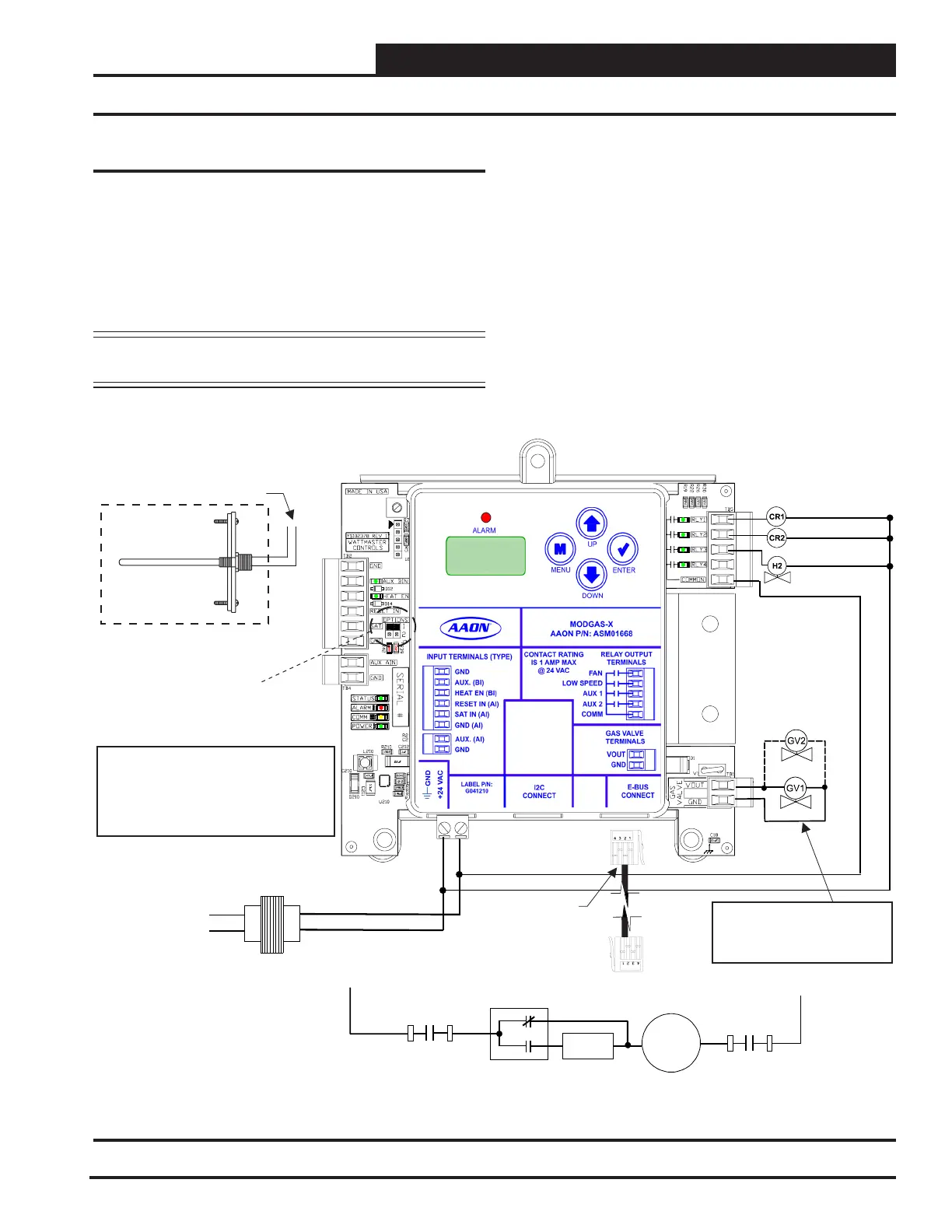
MODGAS-X Controller Wiring
The ASM01668 MODGAS-X Controller is designed to
modulate up to two gas valves to maintain a desired Discharge
Air Temperature. It also controls the speed of the induced
draft fan to maintain proper combustion in the heat exchanger.
The MODGAS-X Controller directly connects to the VCCX2
Controller or indirectly using an E-BUS Expansion Board via
an EBC E-BUS cable. See Figure 42, this page.
NOTE: If using multiple E-BUS Sensors or Modules, the
E-BUS Hub or Adapter Board may be required.
The following information will be passed between the
MODGAS-X controller and the VCCX2 Controller:
• Heat activation command
• Heating Discharge Setpoint
• The oset for the Supply Air Temperature Sensor
• High Limit Temperature Setpoint
• If the communication is interrupted between the
MODGAS-X Controller and the VCCX2 Controller,
the MODGAS-X controller will revert to stand-alone
operation.
For more information, refer to the MODGAS-X Controller
Technical Guide.
Supply
Air Temperature
Sensor
Mount In Supply
Air Duct
Connect Supply Air Temperature
Sensor to AI3 & GND
On VCCX2 Controller
EBC E-BUS Cable
Connects To
VCCX2 Controller’s
Expansion Port
Set Jumper To 1.
Fan Enable
Low Speed Fan
24 VAC power input terminals
maximum power consumption
One Gas Valve = 18 VA
Two Gas Valves = 33 VA
Aux Heat Valve
Note:
1. 24 VAC must be connected so
that all ground wires remain common.
2. All wiring to be in accordance with
local and national electrical codes
and specifications.
18-30 VAC
GND
Two gas valves can
be connected as
shown
Line
Voltage
40 VA
Transformer
Minimum
CR1-B
N.O.
N.O.
N.C.
CR2-1
SC
Speed
Control
Motor
Induced
N.O.
CR1-A
L2
L1
Figure 42: MODGAS-X Controller to VCCX2 Controller Wiring Diagram
WIRING
MODGAS-X Controller

 Loading...


