27
8
3 SET UP MODE
3.1 Introduction
To access the Set Up mode (Levels 2 to 5) the correct password must be entered in the security code frame.
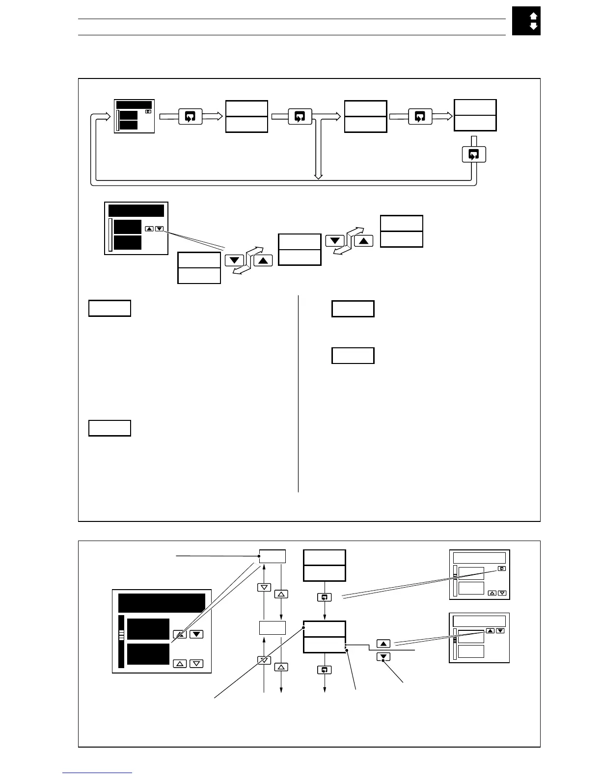
Fig. 3.1 Set Up Mode – Overview
350.0
351.5
70
350.0
351.5
70
50
COdE
OFF
AtNE
LEV1
OPEr
LEV2
LEV5
tUNE
VLVE
LEV1
OPEr
Valid Set Up or
Configuration
password
LEV2
Tuning
Cycle time, output 1 & 2
On/off hysteresis values
Proportional bands 1 to 4
Integral action times 1 to 4
Derivative action times 1 & 2
Manual reset value
Control deadband
Heat Cool Output 1 & 2 Start
LEV3
Set Points
Local set point values 1 to 4
Slave set point value
Remote set point ratio/bias
Ramp rate
LEV4
Alarm Trip Points
Alarm 1 to 8 trip points
LEV5
Motorized Valve Set Up
With feedback:
Feedback ratio/bias
Deadband
Regulator travel time
Boundless:
Deadband
Regulator travel time
Press
and hold
Invalid
password
350.0
351.5
70
350.0
351.5
70
tUNE
LEV.2
1.0
CYC.1
2.01
Frame number
2.xx – Level 2
3.xx – Level 3 etc.
Parameter
Parameter
adjustment
2.00
Default
value
350.0
351.5
70
Fig. 3.2 – Scroll Display Overview