38
4 CONFIGURATION MODE
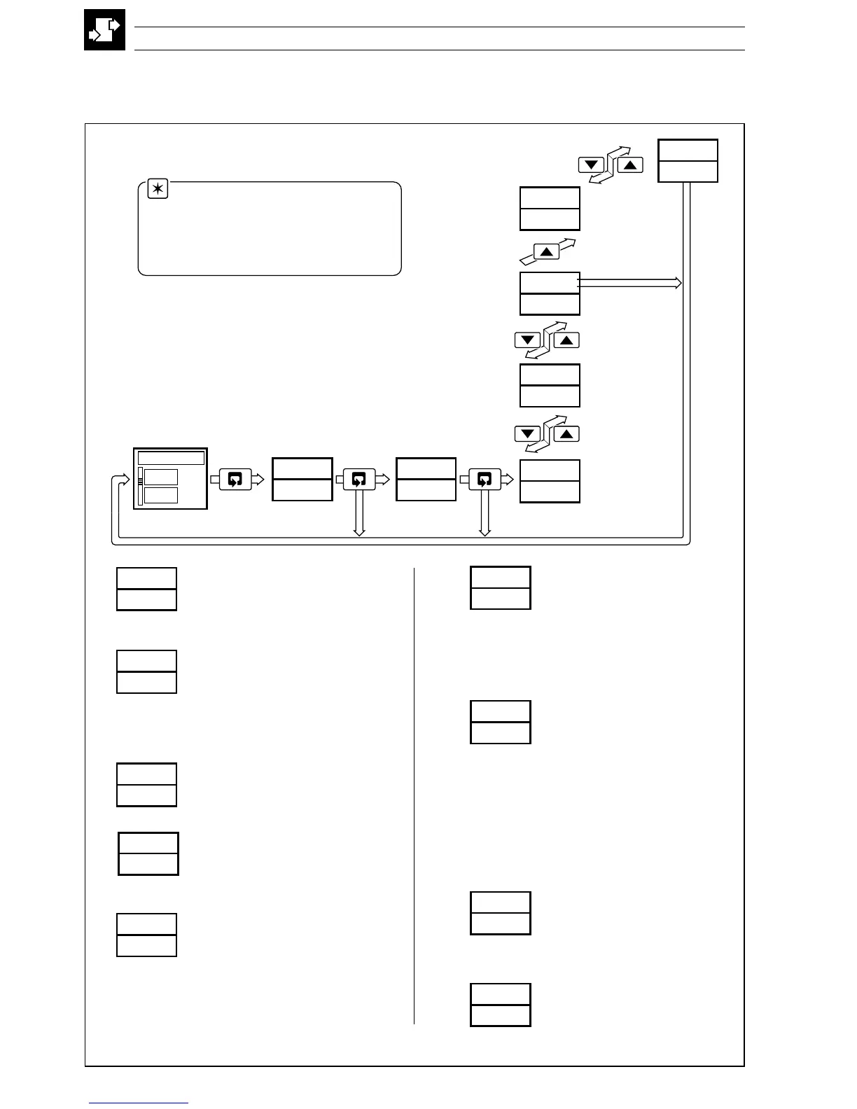
Fig. 4.1 Configuration Mode – Summary
LEV6
Basic Configuration
Template application
Output type
Control action
Mains rejection frequency
LEV7
Analog Inputs 1 to 3
Type
Electrical range
Decimal places
Engineering range
Broken sensor drive
Input filter time constant
LEV9
Set Points
Tracking enable
Set point limits
Local set point sources 1 to 4
Local/remote set point selection
LEV8
Alarms 1 to 8
Type
Trip level
Hysteresis band
LEVA
Control Configuration
Power fail recovery action
Output high/low limits
Slew rate + disable
Configured outputs 1 to 3
Manual output selection sources
Auto mode selection source
Tune parameter sources 1 to 4
LEVb
Operator Configuration
Auto/manual key enables
Local/remote key enables
Alarm acknowledge key enable
Operator set point adjust enable
Operator ratio/bias enable
Password settings
Clock settings
LEVC
Output Assignment
Outputs 1 and 2 type
Digital output
Assignment source
Polarity
Analog output
Assignment source
Electrical range
Engineering range
Relay outputs 1 to 4
Assignment source
Polarity
LEVd
Serial Communications
2-/4-wire connection
2400/9600/19200 baud rate
Parity
Modbus address
LEVE
Calibration
Offset/span adjustment
Motorized valve feedback
APPL
INPt
SEt.P
ALr
CNtL
OPEr
ASSN
SErL
CAL
Valid Set Up or
Configuration
password
Valid
Configuration
password
Press
and hold
LEV1
OPEr
LEV2
tUNE
LEV5
VLVE
LEV6
APPL
50
COdE
OFF
AtNE
Press
and hold
LEVE
CAL
Valid Auto-tune,
Set Up or
Configuration
password
Invalid
password
Autotune
password
Enter the Auto-tune,
Set Up or
Configuration
password
Set Up
password
350.0
351.5
70
4.1 Introduction
To access the Configuration mode (Levels 6 to E) the correct password must be entered in the security code
frame.
Note. When in the configuration
mode, the green bargraph led illuminates.
All relays and digital outputs are de-
energized and all analog outputs revert to
the set minimum current output.