35
8
5.00...5.04
3 SET UP MODE…
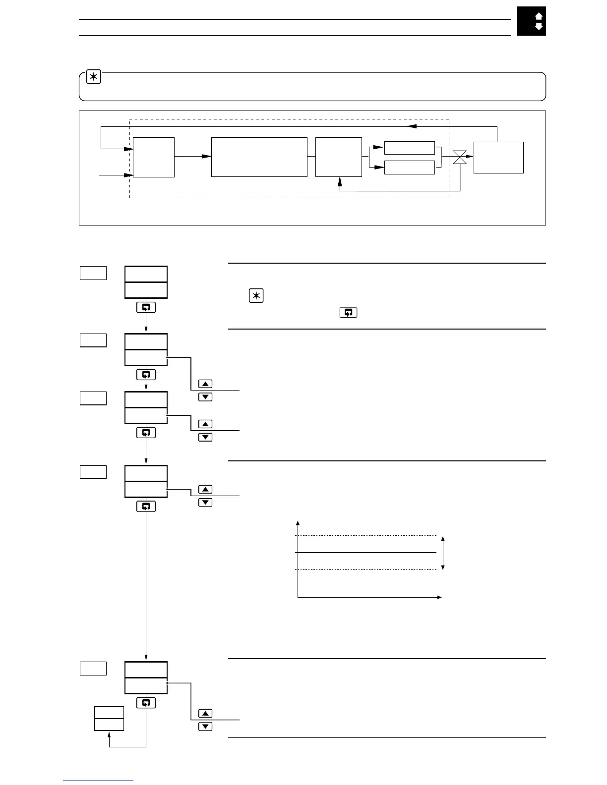
Level 5 – Valve Setup
Note. To select this frame from anywhere in this page,
press and hold the key for a few seconds.
Motorized Valve Ratio and Bias
Desired valve position = (Ratio x PID output) + Bias
Motorized Valve Ratio
[0.01 to 10.00]
Motorized Valve Bias
[–100.0 to 100.0%]
Motorized Valve Deadband
[0.0 to 100% of the position feedback span]
Example. If the valve is set to be driven to the 50% open position
and the deadband is set to 4%, the motor stops driving when the
position feedback is 48%. The deadband is between 48% and 52%.
Regulator Travel Time
The time entered is compared with the actual travel time. If the
valve is sticking an error message is generated.
[0 to 5000 seconds, 0 = no check]
Return to top of page.
U.LU.E
LEV.5
5.00
1..0
d.bnd
5.03
0
VbIA
5.02
0
VrAt
5..01
30
r.trU.
5.04
Position %
Required valve position
Deadband
(centered around
required position)
LEV.5
VLVE
PID
Control
Terms
PV
SPt
Process
Open relay
Valve
Controller
Position Feedback
Close relay
PID
Output
(PID O/P x
V.rAt)
+
V.bIA
3.5.1 Valve Setup (Feedback Types)
3.5 Level 5 – Valve Setup
Note. Level 5 is applicable only for a motorized valve output type – see Section 4.2, Basic
Configuration/ Output Type.
Fig. 3.3 Motorized Valve Output with Feedback – Schematic