80
…5 INSTALLATION
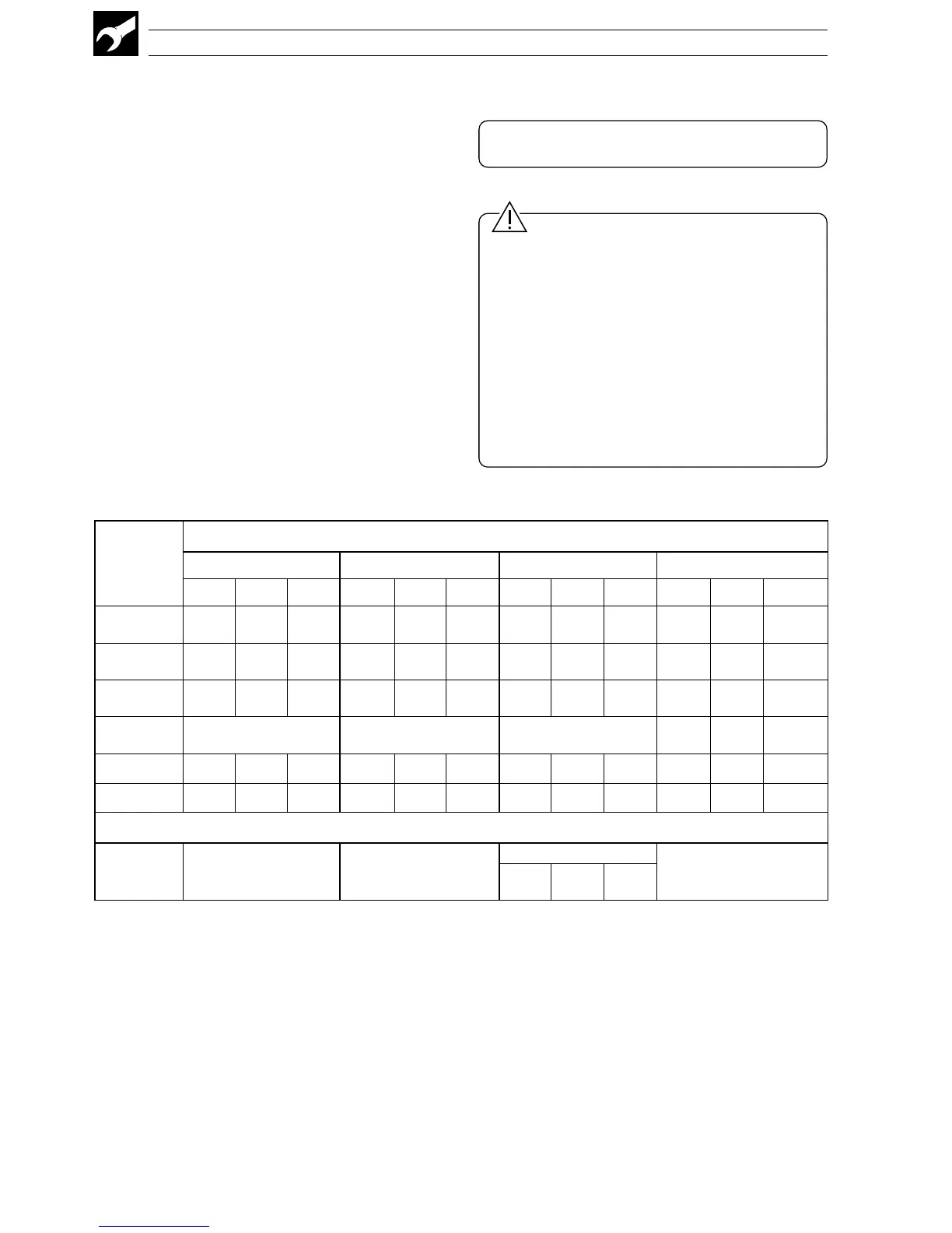
foepyT
-omrehT
elpuoc
elbaCgnitasnepmoC
3481SB1.69CMISNA41734NID03.oNtraP7394SB
+ – esaC+– esaC+– esaC+– esaC
lA-iN/rC-iN
)K(
nworBeulBdeRwolleYdeRwolleYdeRneerGneerGneerGetihW*neerG
lisiN/lisirciN
)N(
egnarOeulBegnarOegnarOdeRegnarO— kniPetihW*kniP
hR-tP/tP
)SdnaR(
etihWeulBneerGkcalBdeRneerGdeRetihWetihWegnarOetihW*egnarO
hR-tP/hR-tP
)B(
–––yerGetihW*yerG
)T(iN-uC/uCetihWeulBeulBeulBdeReulBdeRnworBnworBnworBetihW*nworB
)J(noC/eFwolleYeulBkcalBetihWdeRkcalBdeReulBeulBkcalBetihW*kcalB
stiucricefasyllacisnirtnirofeulBesaC*
)L(noC/eF
–—
01734NID
—
)01734NID(
/eulB
der
eulBeulB
5.7.2 3-lead Resistance
Thermometer (RTD) Inputs
The three leads must have equal resistance, not
exceeding 50Ω each.
5.7.3 2-lead Resistance
Thermometer (RTD) Inputs
If long leads are necessary it is preferable to use a
3-lead RTD. If the RTD is to be used in a hazardous
area, a 3-lead RTD connected via a suitable Zener
barrier, must be used.
5.8 Output Connections
Make connections as shown in Fig 5.6.
Refer to Table B on the rear fold-out for the
default output assignment settings.
5.9 Power Supply Connections
Caution.
• A 1A Type T fuse must be fitted in the live (+ve)
supply line.
• The ground line must be connected to the
ground studs on the terminal block – see
Fig. 5.6.
• Do not disturb the link between the two ground
studs.
• The type of power supply required (AC or DC)
is stated at the time of order and can be
identified from the instrument code number:
C35X/XX0X/STD = 100 to 240 V AC
C35X/XX1X/STD = 24 V DC
Table 5.1 Thermocouple Compensating Cable