Revision: Language: Page:
A EN 7/37
1KHW001493-EN
B Testing Instructions for the ETL600 Rel. 1 Equipment.
B.1 General
Most of the testing for the ETL600 system can be done with assistance of HMI600. For some
adjustments like Tx RF level, Rx RF level etc. the permissible limits are calculated by the HMI600
and displayed in the dialog boxes.
The pilot signal is QPSK modulated to accommodate both Signalling and Embedded Operations
Channel. As a result, the level of the pilot signal changes continuously so that its exact level cannot
be measured.
The Tx filter E5TX and the Rx filter P4RX (if used) have to be tuned before testing.
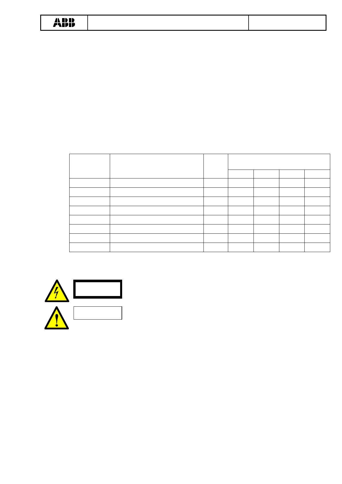
An attenuator with impedance 45, 75 or 125 Ohm and a minimum attenuation of 15 dB is inserted
between two equipments to simulate a power line. For testing, the attenuation between the two
equipments is kept as follows:
Switches of standard ‘80 Watt-
attenuator’ (Minimum = 15 dB)
Max. output
power (PEP)
Equipment type
Attenu
ation
+3 dB +6 dB +10 dB +20 dB
40 W ETL640, 1 channel, no MOD600 31 dB x x
80 W ETL680, 1 channel, no MOD600 34 dB x x x
40 W ETL640, 2 channels, no MOD600 25 dB x
80 W ETL680, 2 channel, no MOD600 28 dB x x
40 W ETL640, 3 channels, no MOD600 21 dB x
80 W ETL680, 3 channels, no MOD600 24 dB x x
40 W ETL640, with MOD600 18 dB x
80 W ETL680, with MOD600 21 dB x
B.1.1 Visual checks before switching ON the equipment.
DANGER
Check the wiring of protective earth to the equipment. Check, if a
protective earth wire of at least 25 mm
2
has been connected visibly to
the earth bolt of the cubicle.
Caution
Check power supply polarity and voltage.
In case of an AC supply, jumpers, located inside of B5LC, had to be set, see
document ‘Instruction for changing the input voltage of B5LC’, 1KHL015788.
In case of battery supply: Check if the positive pole (+) of the battery is grounded. If it is, place an
earth jumper to the positive pole of the cubicle supply.
)
Note: Now switch on the equipment.
B.2 Check power supply B5LA/B5LC
Check the auxiliary supply voltage output of B5LA / B5LC. In case of 80 W units, the supply voltage
for both the upper rack and lower rack must be checked.
There is no access to the internal DC voltages generated by B4LE for the channel subrack.
However, a hardware alarm will be generated if these voltages go outside their limit.