ABB Switzerland Ltd 1KHW001489-EN ETL600
3.5.3.1. DPLC Channel Multiplexer
The multiplexer combines up to 9 individual channels into a single
aggregate channel. The data transfer rate, interface and data transfer
format (synchronous, asynchronous, anisochronous) can be set
individually for each of the individual channels. The aggregate channel
is transmitted trough the MOD600 modem.
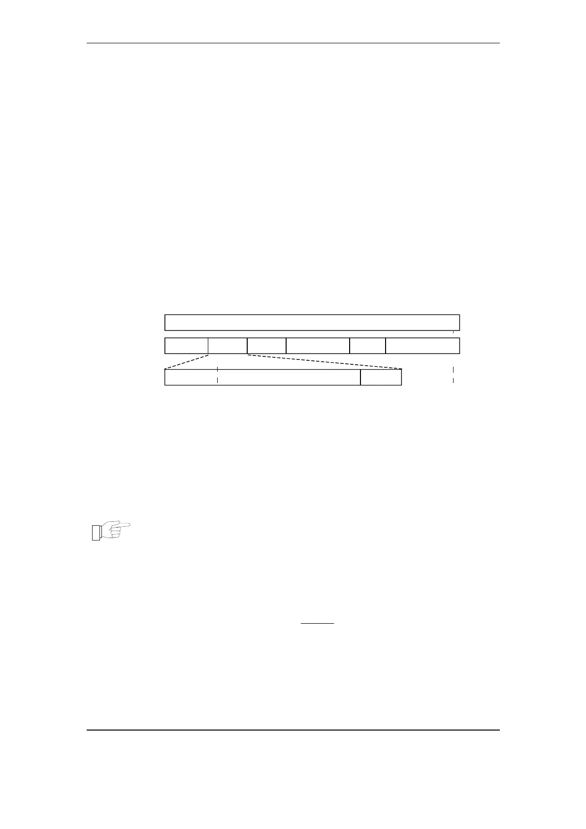
The multiplexer transmitter adds a frame to the aggregate stream of
the MOD600 modem. Each frame has a duration of 10ms. This frame
duration is constant for every MOD600 data transfer rate.
As depicted in Fig. 3-37, the frame comprises a preamble word (PRE)
for synchronization followed by the individual channels (CHx). When
the aggregate data transfer rate is higher than the sum of all individual
channel rates plus the preamble, the frame is filled-up (FIL).
Each individual channel in this frame comprises a user data field
(UDF) of the length of nominal bit rate increased by two bits (ADJ).
This allows speed adjustment for tolerances of connected DTEs
Frame [10 ms duration]
Preamble field (length: 9 bit)
Speed adjustment (length: 2 bit)
Channel x (individual transmission channel)
PRE
DJ
CHx
PRE
CH2CH1
CHn.......
UDF
FIL
DJ
User Data Field (length: nominal bps)UDF
Frame fill-up (length: variable)FIL
Fig. 3-37 DPLC Channel Multiplexer Framing
Note:
When defining the data transfer rate of the aggregate
channel for configuration, note that the framing
overhead depends on the number of individual
channels transmitted.
The required gross data rate for each MOD600 profile can be
calculated according to the following formula:
[] []
[]
[] []
()
Channelsbitbit
ms
bit/seNetDataratbit/sateGrossDatar ×+×+= 29
10
1000
where:
GrossDatarate is the required aggregate rate of MOD600 modem;
NetDatarate is the sum of all individual channel data transfer rates;
3-50 November 2005 Structure and Function