ABB Switzerland Ltd 1KHW001489-EN ETL600
1
2
or
61
2
or
2
12
3
13 9 11
148
5
7
13 9
10
148
2
1
2
or
1
2
or
1
2
or
O
LF
BBO
LF
O
RF
9R 6R 6R 6R 6R 6R14R 5R 6R 6R 9R5R
5
4
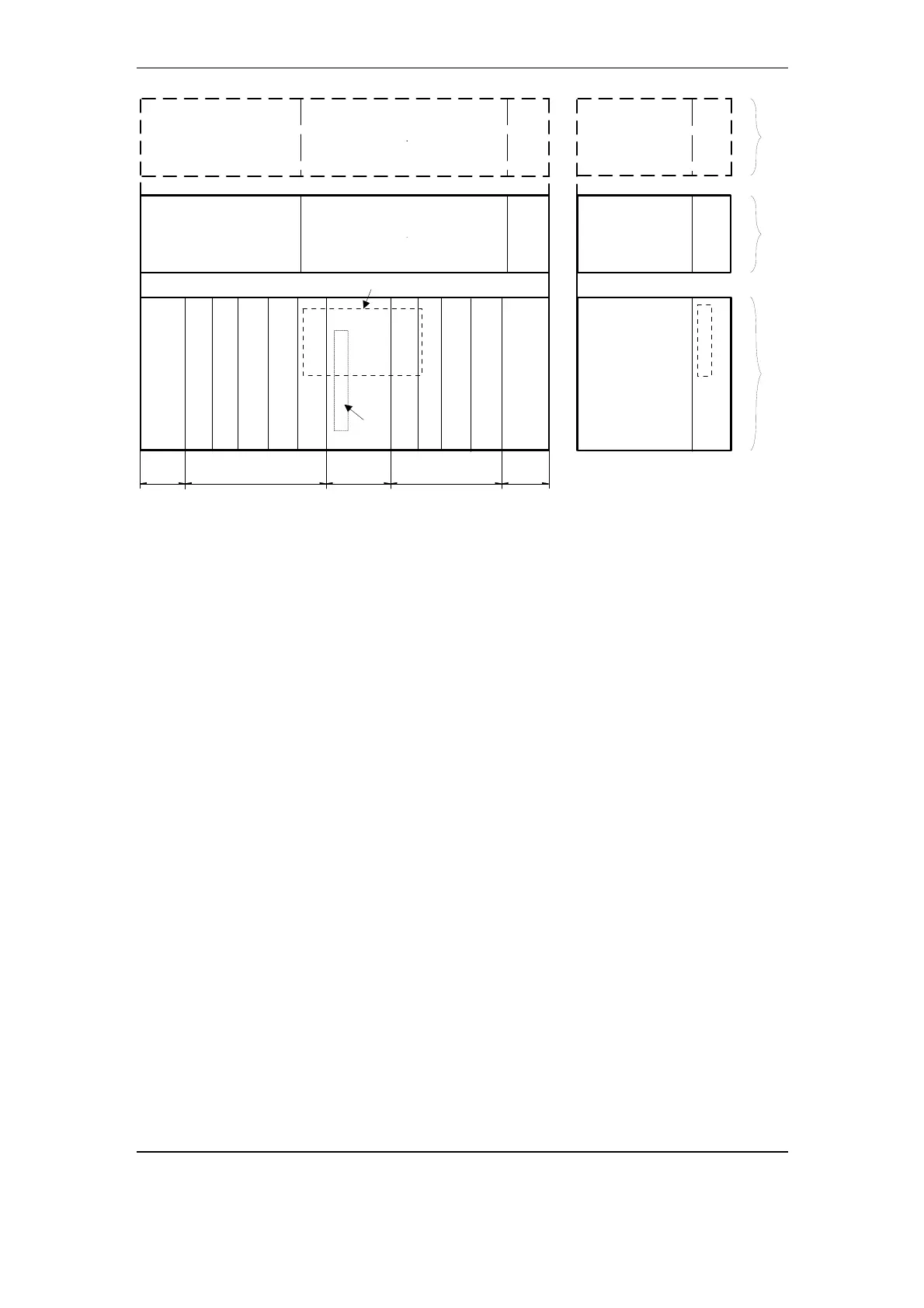
Fig. 3-9 ETL640/680 configurations
Slot types for channel subrack 7 (P7LC), Fig. 3-9:
B: Basic equipment
O
RF
: Optional RF equipment (depending on desired RF-frequencies
and -power)
O
LF
: Optional LF equipment (depending on desired services)
Interface boards 1 (O4LE) and 2 (G4AI) are required to support the
APLC services telephony, teleoperation and teleprotection. These
boards have to be inserted in the foreseen slots O
LF
of the channel
subrack 7. Up to seven interface boards may be inserted in an ETL640
or ETL680. They galvanically separate the interface signals from the
equipment and transform these signals into a form suitable
• for transmission over the equipments Time Division Multiplexing
(TDM) bus and
• for Frequency Division Multiplexing (FDM) into the AF-channel(s),
refer to Fig. 3-5.
The FDM concept allows the available frequency band to be shared
between the teleprotection service and the other services by switching
these off during transmission of teleprotection commands and thus
making the full output power of the PLC equipment available to
teleprotection. This technique is called 'boosting'.
3-12 November 2005 Structure and Function