ETL600 1KHW001489-EN ABB Switzerland Ltd
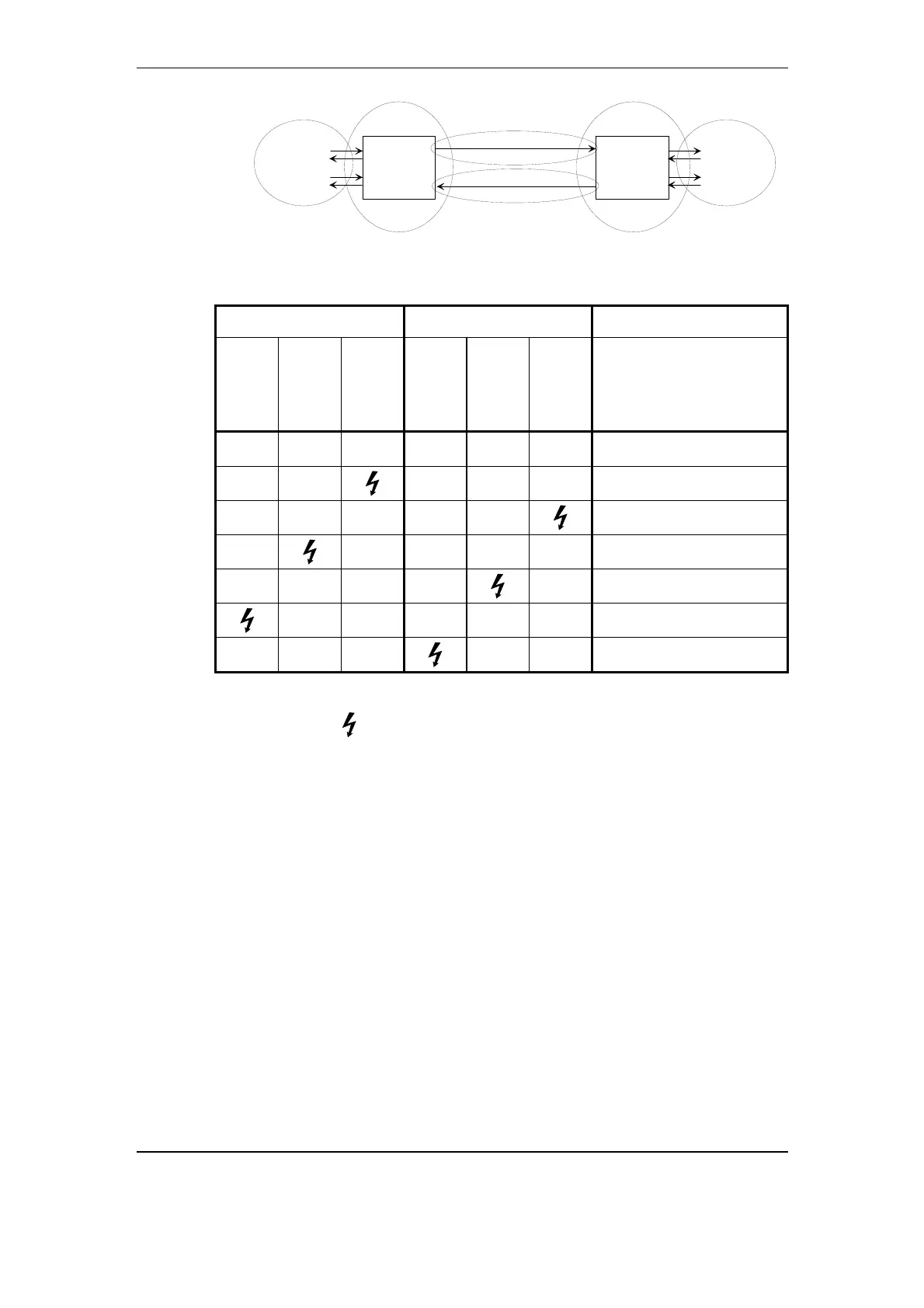
RF channel A to B
Equipment A
ETL600
ETL600
RF channel B to A
Equipment
connected to
B
Equipment
connected to
A
Equipment B
Fig. 9-1 The six major fault location areas of a PLC link
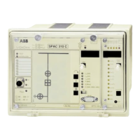
Equipment A Equipment B
Hardware
Alarm
Interface
Alarm
Link
Alarm
Hardware
Alarm
Interface
Alarm
Link
Alarm
Error caused by:
- - - - - -
-
- -
- - -
Channel B to A
- - - - -
Channel A to B
-
- - - -
Equipment connected to A
- - - -
-
Equipment connected to B
x x - - x
Equipment A
- - x
x x
Equipment B
Table 9-2 Fault location of an ETL600 link
Legend:
Alarm present
-
Alarm absent
x
Don’t care
9.3.1. Alarm concept
The concept distinguishes between alarms, warnings and events.
An alarm indicates that the ETL600 system is not functioning
according to specification.
wn in Fig. 9-2, alarms are generated by hardware components
local ETL600 terminal. Some alarms
are exchanged between the local and the remote terminal.
A warning indicates that the ETL600 terminal is not in the normal
operation state. An example for this is when the ETL600 terminal
operates in a test mode.
An event is a snapshot of the alarm state of the ETL600 terminal
recorded together with date and time.
As sho
and by software processes of the
Troubleshooting November 2005 9-5