ABB Switzerland Ltd 1KHW001489-EN ETL600
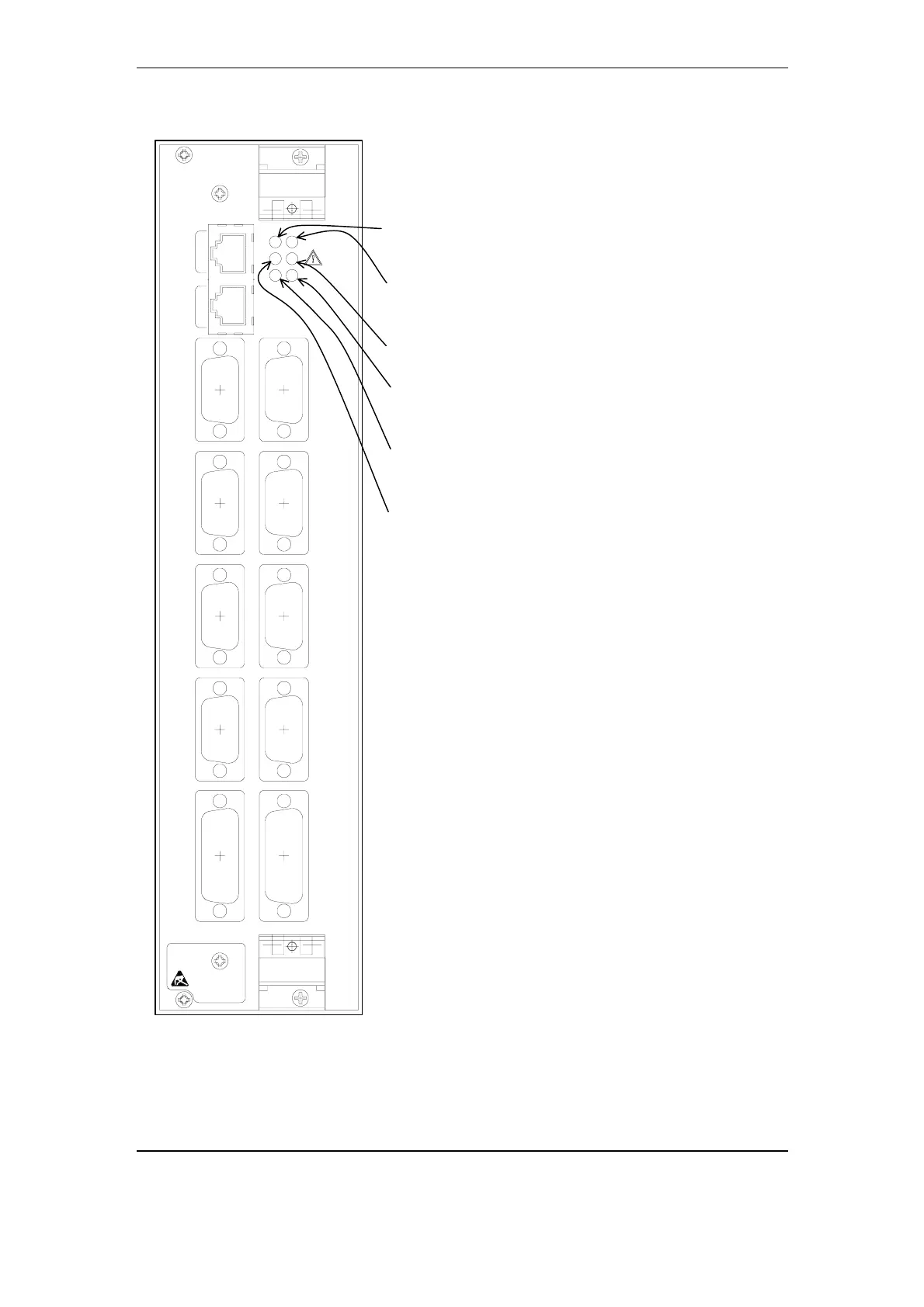
3.3.4.1. Frontplate P4LU
V.24 PORT 4
IRIG-B
V.11 PORT 1 V.24 PORT 2 V.24 PORT 1
V.11 PORT 2 V.24 PORT 5V.24 PORT 6
HMI
V.24 PORT 3
G703.1
DSP
P4LU
LAN
HW
SYS
P4LU
LNK
RDY
'RDY' LED green: System ready
Lights if the ETL600 system is in normal
operation.
'P4LU' LED red: Module hardware alarm
Lights if a hardware alarm on P4LU is
detected.
'SYS' LED red: Cabinet alarm / System alarm
Lights if a system alarm is present.
'HW' LED red: Hardware alarm
Lights if a hardware alarm on one or more
of the ETL600 modules is detected.
'LINK' LED red: Link alarm
Lights if the link for either channel 1, 2 or
3 is disturbed.
'U ' LED yellow: System warning
Lights if the system is not in normal
operation mode and no system alarm is
present.
‘LAN’ Socket for LAN port (not supported with
ETL600 Release 1)
‘G.703’ Socket for G.703 port (not supported with
ETL600 Release 1)
'HMI' Socket for HMI communication port
(9 pin RS-232 configured as DCE)
'IRIG-B' Socket for IRIG-B input for RTC
synchronization
'V.24 PORT 1' Socket for V.24 data port 1
'V.24 PORT 2' Socket for V.24 data port 2
'V.24 PORT 3' Socket for V.24 data port 3
'V.24 PORT 4' Socket for V.24 data port 4
'V.24 PORT 5' Socket for V.24 data port 5
'V.24 PORT 6' Socket for V.24 data port 6
'V.11 PORT 1' Socket for V.11 data port 1
'V.11 PORT 2' Socket for V.11 data port 2
Fig. 3-16 Frontplate P4LU
3-26 November 2005 Structure and Function