ABB Switzerland Ltd 1KHW001489-EN ETL600
signal of the first link must not be forwarded to the second link since
each link maintains its own pilot channel independent of the others.
A
transit filter has to be used that passes the desired data frequencies but
blocks the pilots.
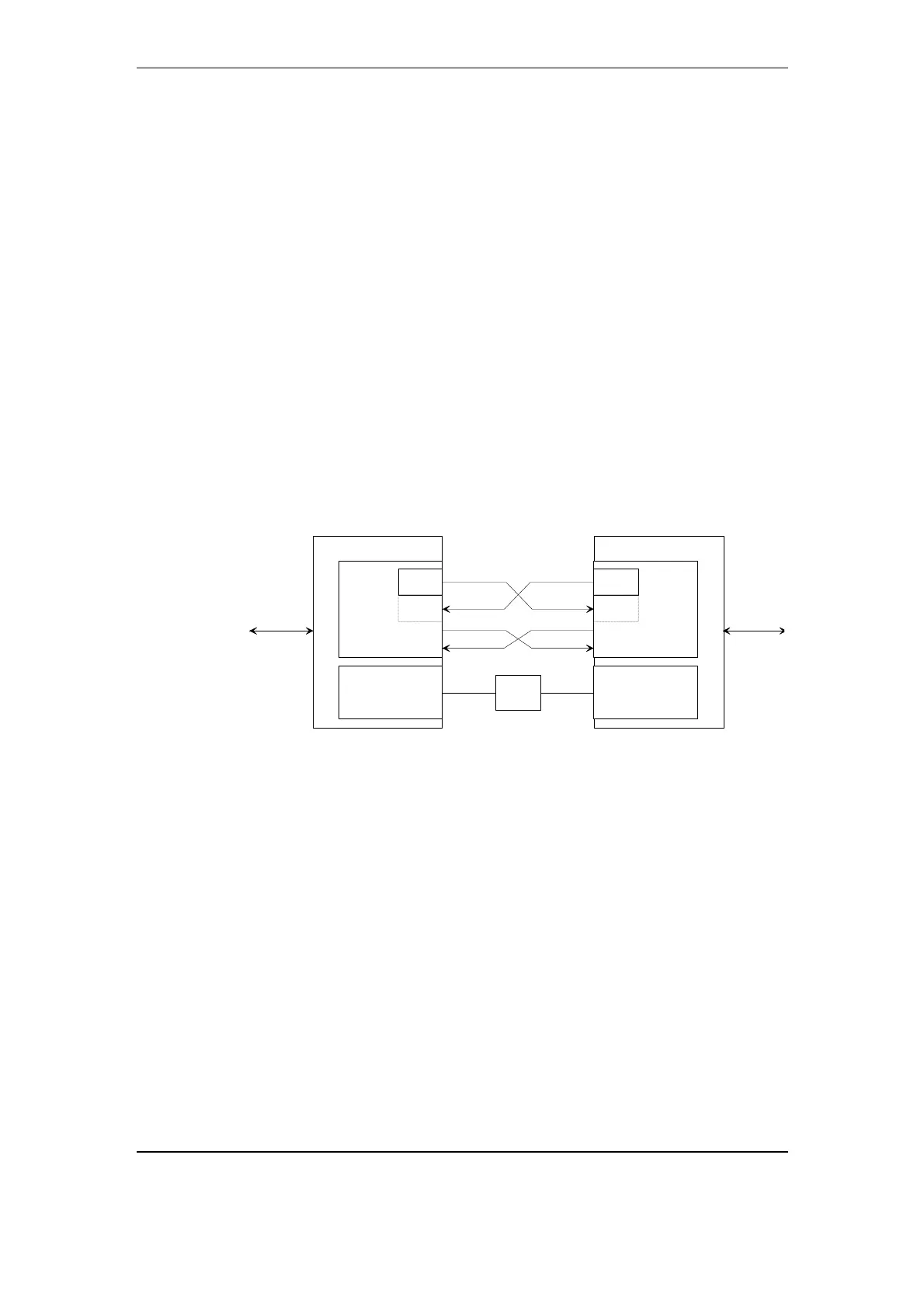
By connecting
• E-wire and M-wire of the two equipment for out of band signaling,
• the HMI ports of the two equipment via Null modem or RS-485
station bus for management data,
information carried by the pilot channel can still be forwarded to the
other link. The necessary connections are indicated in Fig. 3-35.
Several possibilities exist for the placement of the transit filters:
1. in the AF outputs of both equipment,
2. in the AF inputs of both equipment,
3. in the AF in- and outputs of both equipment.
The first possibility is the standard solution. If for some reason this is
not possible, or if noise picked up on the AF line connecting the two
equipment has to be suppressed, possibilities 2 or 3 have to be
chosen. Note that each transit filter adds its group delay response to
the overall group delay response of the links.
O4LE
Null-
modem
ETL600
Transit-
filter
AF out AF out
AF inAF in
E-Wire E-Wire
M-WireM-Wire
HMI HMI
ETL600
O4LE
P4LTP4LT
Transit-
filter
Transit-
filter
Transit-
filter
RF RF
Fig. 3-35 Transit connection
In the signal path of each input port, a programmable
attenuator/amplifier is provided, to adapt the signal level at the port to
the internal level of the ETL600. On the output side, a similar
programmable attenuator/amplifier restores the signal strength to the
level required at the output port.
3.4.3. External teleprotection
At most one teleoperation port per APLC channel can be configured
for connection to the external teleprotection equipment type NSD570
or NSD70C. The ETL600 does not squelch the signal coming from the
opposite external teleprotection equipment during periods of excessive
line noise. An external boost input, whose polarity can be inverted if
desired, is available for each external teleprotection port. If this input is
enabled, the NSD570/NSD70C signal fed into the port is boosted by
up to 9 dB and all disconnectable input signals are disconnected as
long as the external boost input is activated. By disabling the external
3-44 November 2005 Structure and Function