ETL600 1KHW001489-EN ABB Switzerland Ltd
3.3.12. Receive Filter P4RX
The receive filter is primarily used for the suppression of local and
parallel transmitter signals. It is plugged in the rightmost slot of the
channel rack P7LC. When it is unplugged, the filter input pins are
automatically connected to the filter output pins on the backplane of
P7LC. The filter can be programmed to bandwidths 8, 16 or 32 kHz.
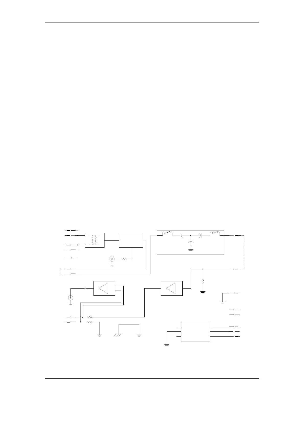
Fig. 3-24 shows the block diagram. The input signal to the filter arrives
from the RF hybrid, having passed the Rx level adjustment
potentiometer. An attenuation circuit at the input ensures a defined
load impedance for the following receive filter, that is almost
independent of the potentiometer setting. The bandpass receive filter
obtains an input selectivity and suppresses primarily the transmitter
signals of the local parallel PLC equipment. The structure of the two-
stage filter was chosen such that together with the tuning adapter
P4LM, a simple tuning on site is possible.
A low noise, low distortion amplifier compensates for attenuation and
filter losses, to achieve an input to output board gain of 0 dB.
The RXRF-IN coax connector on the front panel allows monitoring of
the incoming Rx signal. It is not decoupled and thus can be used as a
test input for the filter.
The RXRF-OUT coax connector on the front panel (decoupled,
50 Ohm) monitors the output voltage to the signal processing unit.
Center frequency and bandwidth of the filter are programmed by
means of jumpers on the board. Fine tuning is done by adjusting L1
and L2 with the help of the tuning adapter P4LM. For details, refer to
the P4RX Tuning Instructions in the annex.
attenuator
1MHz low pass filter
filter termination
power supply
voltage regulators
input transformer
amplifier
Rx-filter
termination
resistor
+ 5V
- 5V
RxRF IN
RxRF OUT
+12.8V
-12.8V
GND
input 600 Ohm
balanced
TUNE- F1
TUNE-F3
PLUG-OUT4
L1
L2
Rx-filter
RXRF-IN-A
RXRF-IN-B
RXRF-OUT-A
RXRF-OUT-B
T-OUT
TUNE- F2
V-IN
TXRF-A
TXRF-B
A1
B4
B6
C1
A4
C4
A2
B5
B7
C27
A27
A8
C9
C10
A/C/24/25
A/C/22/23
see backplane P1LC
1.)
1.)
2.)
2.)
1.) A1 and C1 used for Rx filter test with tuning adapter P4LM
2.) connected on backplane P1LC, or on tuning adapter in position "filter"
50
50
diff amplifier
chassis
not used
not used
Cs1
Cs2
Cp
Fig. 3-24 Block diagram of the Rx filter P4RX
Structure and Function November 2005 3-35