ETL600 1KHW001489-EN ABB Switzerland Ltd
3.3.5. Alarm relay module R1BC
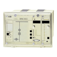
The alarm relay module type R1BC is mounted on the back of the
backplane P1LC of the ETL600 channel tier P7LC.
8 power relays are mounted on the alarm relay module. Each of the
relays can be programmed by jumpers on R1BC individually to one of
three alarm sources: User alarms 1, 2 or 3.
Since each of the 8 relays is connected to three terminals, it is
possible to use the relays individually as contact open (NO: contact
open in case of alarm) or contact closed (NC: contact closed in case of
alarm).
User alarms 1,2 and 3 mentioned above are configurable by HMI600
via dialog-box 'Alarm relays on R1BC'. Various alarm sources from the
local and the remote equipment can be selected for each of the user
alarms. If several alarm sources are selected for a particular user
alarm, these sources are summed (e.g. combined by a logical OR-
function) to form the user alarm.
Programming of the jumpers on R1BC is done as follows:
• To program relay N to user alarm 1: insert jumper CA-N
• To program relay N to user alarm 2: insert jumper R1-N
• To program relay N to user alarm 3: insert jumper R2-N
where N is a number between 1 and 8.
Example:
If it is required that the link alarm criteria of the local and remote equipment
are to be made available as a closed and as an open contact in case of alarm,
we first program user alarm 1 with the HMI600 by crossing the 2 checkboxes
associated to 'Alarm 1/Local equipment/PLC link alarm' and 'Alarm 1/Remote
equipment/PLC link alarm'. Next, we program relays 5 and 6 to user alarm 1
by inserting jumpers R1-5 and R1-6 on R1BC. A link alarm on either
equipment - local or remote - is now indicated by a closed contact between
terminals 2 and 3 of connector X5, and as an open contact between terminals
1 and 2 of connector X6.
The connection to the relay contacts can be made directly at the
terminals of the alarm relays module itself, or via the alarm cable
V9OT on the terminal block at the rear of the cabinet.
Structure and Function November 2005 3-27