ABB Switzerland Ltd 1KHW001489-EN ETL600
NO NC
NO NC
NO NC
NO NC
NONC
NONC
NONC
NONC
K1
k1
K2
k2
K3
k3
K4
k4
K5
k5
K6
k6
K7
k7
K8
k8
R1-1
R2-1
CA-1
CA-5
R1-5
R2-5
R1-2
R2-2
CA-2
CA-6
R1-6
R2-6
R1-3
R2-3
CA-3
CA-7
R1-7
R2-7
R1-4
R2-4
CA-4
CA-8
R1-8
R2-8
R1BC
R1BC_block_.DSF
X1
X2
3
2
1
3
2
1
3
2
1
3
2
1
X4
X3
3
2
1
X8
X7
3
2
1
X6
3
2
1
3
2
1
X5
X40
2
6
4
250V
150W
2000VA
250V
150W
2000VA
250V
150W
2000VA
250V
150W
2000VA
250V
150W
2000VA
250V
150W
2000VA
250V
150W
2000VA
250V
150W
2000VA
User alarm 2
From P4LT
User alarm 3
User alarm 1
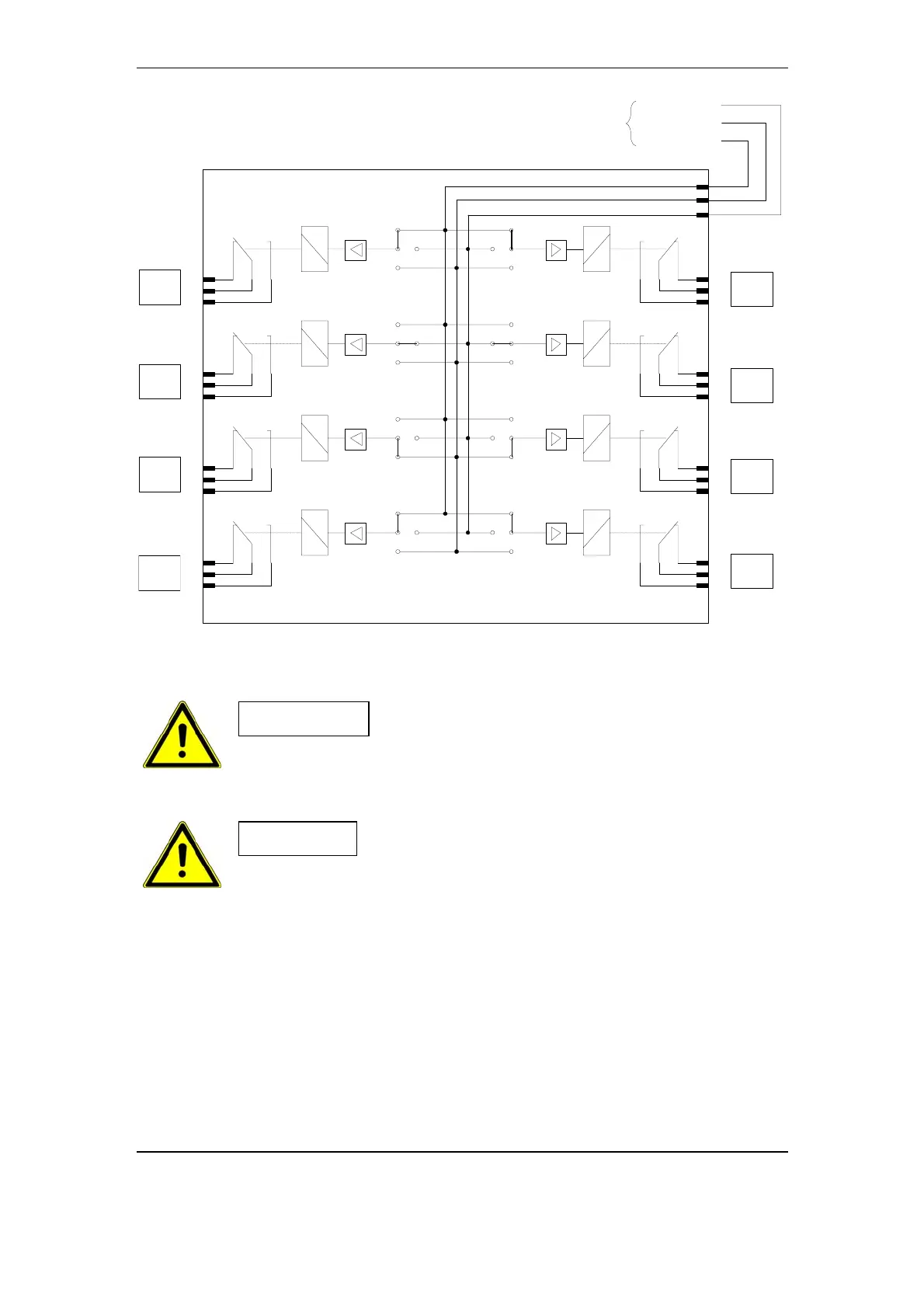
Fig. 3-17 R1BC Block Diagram
Caution
Connecting a load between terminals 1 and 3 of
connectors X1, X2, X3, X4, X5, X6, X7 or X8 on
R1BC is not allowed. Instead, connect the load
either between terminals 1 and 2 or between 2 and
3 of these connectors.
Caution
Power supplies connected to alarm relay contacts
must be short circuit and over current protected.
3-28 November 2005 Structure and Function