ETL600 1KHW001489-EN ABB Switzerland Ltd
125 Ohm
75 Ohm
45 Ohm
line output
to coax
T3
T3A2
T3A3
T3A1
T3B3
T3B2
T3B1
T1
d/b/z20
d/b/z16
T4B3
T4
T4A1
T4B1
T4A2
T4A3
T4B2
d/b/z28
T2
hybrid
transformer
operating mode
H6
H3
H5
H4
H2
H1
S1
S2
RX level
Alarm circuit
divider, frequency compensation
RF Line Monitor
100W=0dBm
@ 50 Ohm
(50dB below line
dbz20)
z12
selective
supervision
d6
TXRF Power Alarm
d/b/z30
z8
z6
+12.8V
45 Ohm
75 Ohm
125 Ohm
K1,
45
Ohm
K3,
125
Ohm
K2,
75
Ohm
d12
b12
RA
RD
R228
Line Balancing Network
L1
LA LN
LP
park position
K1
z2 / b2
TX relay
Default jumpers shown, K1 not energized
CA CL
CECD
Amplifier
d7b/z26
d/b/z32
common
RX RF signal
Amplifier alarm
Tx ALARM
M1
M2
M3
d/b/z14
TX Filter
z10
GND P7LB (CE)
TX Filter
TX Filter
Amplifier
R125
RP
park position
CB
d8
d10
plug out
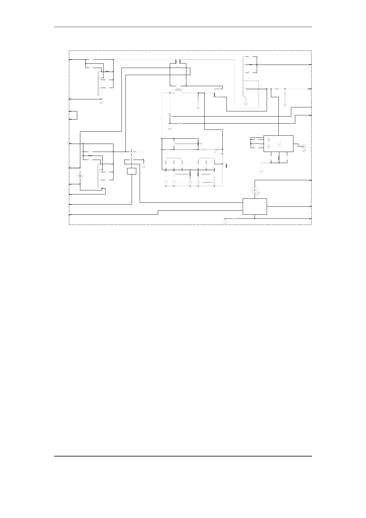
Fig. 3-22 Block diagram RF hybrid P3LE
Additional functions of this module:
• Impedance matching for the Tx filter of the ETL (transformers T3
and T4)
• Preventing of interaction with parallel ETL systems in case of
malfunction or deactivation of the own high power amplifier (relay
K1).
• Protection of the high power amplifier against transient
overvoltages on the line
• Supervision of the high power amplifier and alarm generation in
case of malfunction. The alarm is signaled to the P4LT module and
indicated by a LED on the front plate.
With the jumpers H1 to H6, S1 and S2, two topologies of the RF front
end can be selected:
• Inserting jumpers H1, H2, H3, S1 selects the topology according to
Fig. 3-23a, while
• Inserting jumpers H4, H5, H6, S2 selects the topology according to
Fig. 3-23b.
Structure and Function November 2005 3-33